Sony HCD-SH2000 Service Manual - Page 4
Hcd-sh2000, Servicing, Notes - model
 |
View all Sony HCD-SH2000 manuals
Add to My Manuals
Save this manual to your list of manuals |
Page 4 highlights
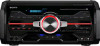
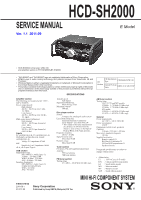
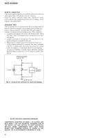
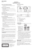
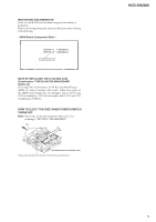
HCD-SH2000 Ver. 1.1 SECTION 1 SERVICING NOTES Notes on chip component replacement • Never reuse a disconnected chip component. • Notice that the minus side of a tantalum capacitor may be damaged by heat. MODEL IDENTIFICATION - BACK PANEL - Flexible Circuit Board Repairing • Keep the temperature of the soldering iron around 270 °C during repairing. • Do not touch the soldering iron on the same conductor of the circuit board (within 3 times). • Be careful not to apply force on the conductor when soldering or unsoldering. UNLEADED SOLDER Boards requiring use of unleaded solder are printed with the leadfree mark (LF) indicating the solder contains no lead. (Caution: Some printed circuit boards may not come printed with the lead free mark due to their particular size) : LEAD FREE MARK Unleaded solder has the following characteristics. • Unleaded solder melts at a temperature about 40 °C higher than ordinary solder. Ordinary soldering irons can be used but the iron tip has to be applied to the solder joint for a slightly longer time. Soldering irons using a temperature regulator should be set to about 350 °C. Caution: The printed pattern (copper foil) may peel away if the heated tip is applied for too long, so be careful! • Strong viscosity Unleaded solder is more viscous (sticky, less prone to flow) than ordinary solder so use caution not to let solder bridges occur such as on IC pins, etc. • Usable with ordinary solder It is best to use only unleaded solder but unleaded solder may also be added to ordinary solder. CAUTION Use of controls or adjustments or performance of procedures other than those specified herein may result in hazardous radiation exposure. NOTES ON HANDLING THE OPTICAL PICK-UP BLOCK OR BASE UNIT The laser diode in the optical pick-up block may suffer electrostatic break-down because of the potential difference generated by the charged electrostatic load, etc. on clothing and the human body. During repair, pay attention to electrostatic break-down and also use the procedure in the printed matter which is included in the repair parts. The flexible board is easily damaged and should be handled with care. NOTES ON LASER DIODE EMISSION CHECK The laser beam on this model is concentrated so as to be focused on the disc reflective surface by the objective lens in the optical pickup block. Therefore, when checking the laser diode emission, observe from more than 30 cm away from the objective lens. This appliance is claassified as a CLASS 1 LASER product. This label is located on the rear exterior. PART No. Model E2, E51, EA, MY, SAF MX Part No. 4-275-656-0[] 4-275-656-1[] • Abbreviation E2 : 120 V AC area in E model E51 : Chilean and Peruvian models EA : Saudi Arabian model MX : Mexican model MY : Malaysia model SAF : South African model PLAYABLE DISC Format of discs • AUDIO CD Logo • CD-R/-RW in AUDIO CD format • CD-R/-RW in DATA CD format, containing MP3 audio tracks 1) that conforms to ISO 9660 2) Level 1/Level 2, Joliet (in expansion format), or Multi Session 3) 1) MP3 (MPEG 1 Audio Layer 3) is a standard format defined by ISO/MPEG which compresses audio data. MP3 audio tracks must be in MPEG 1 Audio Layer 3 format. 2) A logical format of files and folders on CD-ROMs, defined by ISO (International Organization for Standardization). 3) This is a recording method that enables adding of data using the Track-At-Once method. Conventional discs begin at a disc control area called the Lead-in and end at an area called Lead-out. A Multi Session disc is a disc having multiple sessions, with each segment from Lead-in to Lead-out regarded as a single session. NOTE OF REPLACING THE IC102 AND IC4605 ON THE DMB21 BOARD IC102 and IC4605 on the DMB21 board cannot exchange with single. When these parts on the DMB21 board are damaged, exchange the entire mounted board. NOTE OF REPLACEMENT OF THE MS-214 BOARD When the MS-214 board is defective, exchange the entire MD (AU) ASSY. 4
-
 1
1 -
 2
2 -
 3
3 -
 4
4 -
 5
5 -
 6
6 -
 7
7 -
 8
8 -
 9
9 -
 10
10 -
11
-
12
-
13
-
14
-
15
-
16
-
17
-
18
-
19
-
20
-
21
-
22
-
23
-
24
-
25
-
26
-
27
-
28
-
29
-
30
-
31
-
32
-
33
-
34
-
35
-
36
-
37
-
38
-
39
-
40
-
41
-
42
-
43
-
44
-
45
-
46
-
47
-
48
-
49
-
50
-
51
-
52
-
53
-
54
-
55
-
56
-
57
-
58
-
59
-
60
-
61
-
62
-
63
-
64
-
65
-
66
-
67
-
68
-
69
-
70
-
71
-
72
-
73
-
74
-
75
-
76
-
77
-
78
-
79
-
80
-
81
-
82
-
83
-
84
-
85
-
86
-
87
-
88
 |
 |