Sony HT-RT3 Operating Instructions - Page 22
Saving power in standby mode, Mounting the Bar Speaker and the Surround Speakers on a wall - 5 1 sound bar
 |
View all Sony HT-RT3 manuals
Add to My Manuals
Save this manual to your list of manuals |
Page 22 highlights
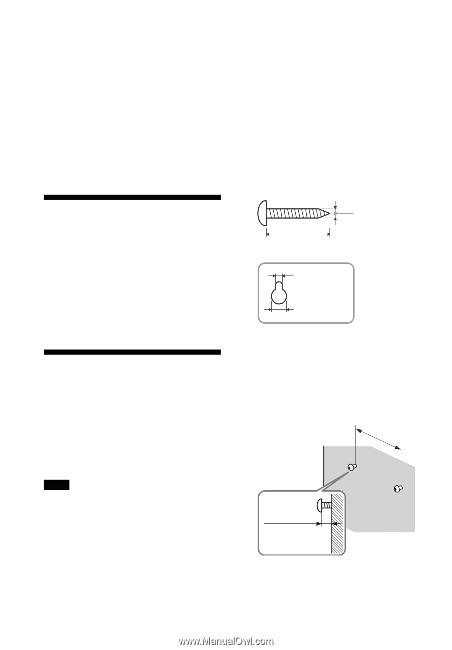
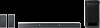
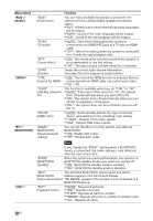
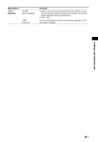
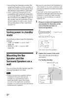
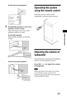
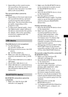
Sound may be interrupted when the sampling frequency or the number of channels of audio output signals from the playback equipment is switched. If the connected equipment is not compatible with copyright-protection technology (HDCP), the image and/or the sound from the HDMI OUT jack of this system may be distorted or may not be output. In such a case, check the specifications of the connected equipment. Be sure to subcontract the installation to Sony dealers or licensed contractors and pay special attention to safety during the installation. Sony shall not be held responsible for accidents or damage caused by improper installation, insufficient wall strength, improper screw installation or natural calamity, etc. 1 Prepare screws (not supplied) that are suitable for the holes at the rear of the Bar Speaker or Surround Speakers. Saving power in standby mode Check that you have made the following settings: "CTRL" in "HDMI>" is set to "OFF" (page 18). "BTSTB" in "BT >" is set to "OFF" (page 18). Mounting the Bar Speaker and the Surround Speakers on a wall 4 mm (3/16 in) More than 30 mm (1 3/16 in) 5 mm (7/32 in) 9.5 mm (3/8 in) Hole at the rear of the speakers 2 Fasten the screws in the wall. The screw should protrude as illustration. For the Bar Speaker 600 mm (23 5/8 in) You can mount the Bar Speaker and the Surround Speakers on a wall. Notes Prepare screws (not supplied) that are suitable for the wall material and strength. As a plasterboard wall is especially fragile, attach the screws securely in the wall beam. Install the speakers on a vertical and flat wall where reinforcement is applied. 6 mm to 7 mm (1/4 in to 9/32 in) 22US
-
 1
1 -
2
-
3
-
4
-
5
-
6
-
7
-
8
-
9
-
10
-
11
-
12
-
13
-
14
-
15
-
16
-
 17
17 -
 18
18 -
 19
19 -
 20
20 -
 21
21 -
 22
22 -
 23
23 -
 24
24 -
 25
25 -
 26
26 -
 27
27 -
28
-
29
-
30
-
31
-
32
-
33
-
34
-
35
-
36
-
37
-
38
-
39
-
40
-
41
-
42
-
43
-
44
-
45
-
46
-
47
-
48
-
49
-
50
-
51
-
52
-
53
-
54
-
55
-
56
-
57
-
58
-
59
-
60
-
61
-
62
-
63
-
64
-
65
-
66
-
67
-
68
-
69
-
70
-
71
-
72
-
73
-
74
-
75
-
76
-
77
-
78
-
79
-
80
-
81
-
82
-
83
-
84
-
85
-
86
-
87
-
88
-
89
-
90
-
91
-
92
-
93
-
94
-
95
-
96
-
97
-
98
-
99
-
100
-
101
-
102
-
103
-
104
 |
 |