Sony KDS-R60XBR1 Operating Instructions - Page 74
Notes on Using This Connection, Notes on Connecting i.LINK Devices, Rear of TV
 |
UPC - 027242681118
View all Sony KDS-R60XBR1 manuals
Add to My Manuals
Save this manual to your list of manuals |
Page 74 highlights
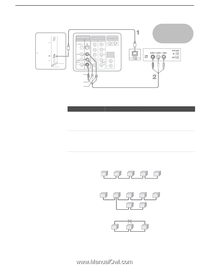
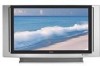
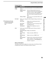
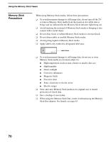
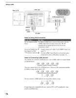
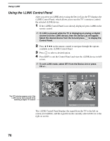
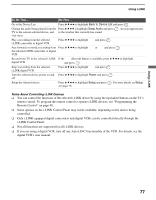
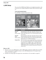
Using i.LINK Rear of TV DIGITAL AUDIO (OPTICAL) OUT PCM/DOLBY DIGITAL S400 i.LINK (DV/HDV/MICROMV/TV) i.LINK cable VIDEO IN 1 3 HD/DVD IN (1080i/720p/480p/480i) 4 5 CONTROL S IN OUT AUDIO OUT (VAR/FIX) Cables are often colorcoded to connectors. Connect red to red, white to white. i.LINK-equipped device AUDIO-R AUDIO-L VIDEO A/V cable Notes on Using This Connection To Do This ... Do This ... Set up a digital i.LINK For digital i.LINK devices (devices that require only the device i.LINK connection), no setup is necessary. The TV automatically recognizes the device as soon as the connection is made. Set up an i.LINK device 1 that supports an EIA- 775A analog connection 2 Connect analog A/V cables to the VIDEO 3 input (see page 73). Use the i.LINK Control Panel to activate the analog connection to your i.LINK device (see page 75). Notes on Connecting i.LINK Devices To connect two or more i.LINK devices, use i.LINK cables to connect them as shown below. A B i.LINK C i.LINK D i.LINK E i.LINK You can connect up to 63 i.LINK devices. However, the maximum number of cables in any serial route is 16. A B i.LINK C i.LINK D i.LINK E i.LINK F i.LINK G i.LINK Do not connect i.LINK devices in a way that creates a loop. i.LINK A B i.LINK C i.LINK Connecting non-compatible devices, such as PCs or PC peripherals, may result in malfunctions. 74
-
 1
1 -
2
-
3
-
4
-
5
-
6
-
7
-
8
-
9
-
10
-
11
-
12
-
13
-
14
-
15
-
16
-
17
-
18
-
19
-
20
-
21
-
22
-
23
-
24
-
25
-
26
-
27
-
28
-
29
-
30
-
31
-
32
-
33
-
34
-
35
-
36
-
37
-
38
-
39
-
40
-
41
-
42
-
43
-
44
-
45
-
46
-
47
-
48
-
49
-
50
-
51
-
52
-
53
-
54
-
55
-
56
-
57
-
58
-
59
-
60
-
61
-
62
-
63
-
64
-
65
-
66
-
67
-
68
-
 69
69 -
 70
70 -
 71
71 -
 72
72 -
 73
73 -
 74
74 -
 75
75 -
 76
76 -
 77
77 -
 78
78 -
 79
79 -
80
-
81
-
82
-
83
-
84
-
85
-
86
-
87
-
88
-
89
-
90
-
91
-
92
-
93
-
94
-
95
-
96
-
97
-
98
-
99
-
100
-
101
-
102
-
103
-
104
-
105
-
106
-
107
-
108
-
109
-
110
-
111
-
112
-
113
-
114
-
115
-
116
-
117
-
118
-
119
-
120
 |
 |