Sony MZ-R30 Service Manual - Page 61
Service Manual
 |
View all Sony MZ-R30 manuals
Add to My Manuals
Save this manual to your list of manuals |
Page 61 highlights
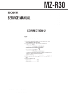
MZ-R30 SERVICE MANUAL 2001.01 US Model Canadian Model AEP Model UK Model E Model Australian Model Tourist Model CORRECTION-2 Correct your Service Manual as shown below. ! r : indicates corrected portion (Service Manual See page 29) 5-3. Precautions for Adjustment 1) Perform all adjustments in the order given in the test mode. After adjusting, exit the test mode. 2) Use the following tools and measuring instruments. • CD test disc TDYS-1 (Parts Code : 4-963-646-01) • SONY MO disc available on the market. $ • Laser power meter LPM-1 (Parts Code : J-2501-046-A) • Oscilloscope (Frequency band above 40MHz. Perform the calibration of probe first before measuring.) • Digital voltmeter 3) Unless specified otherwise, supply DC 6V from the DC IN 6V jack. 4) Switch, knob positions Hold switch OFF AVLS switch OFF 9-923-089-92 2001A0200-1 © 2001.1 Sony Corporation Audio Entertainment Group General Engineering Dept.
-
 1
1 -
2
-
3
-
4
-
5
-
6
-
7
-
8
-
9
-
10
-
11
-
12
-
13
-
14
-
15
-
16
-
17
-
18
-
19
-
20
-
21
-
22
-
23
-
24
-
25
-
26
-
27
-
28
-
29
-
30
-
31
-
32
-
33
-
34
-
35
-
36
-
37
-
38
-
39
-
40
-
41
-
42
-
43
-
44
-
45
-
46
-
47
-
48
-
49
-
50
-
51
-
52
-
53
-
54
-
55
-
 56
56 -
 57
57 -
 58
58 -
 59
59 -
 60
60 -
 61
61 -
 62
62
 |
 |