Sony MZ-RH1 Service Manual - Page 7
Cabinet, Front, Board - driver
 |
View all Sony MZ-RH1 manuals
Add to My Manuals
Save this manual to your list of manuals |
Page 7 highlights
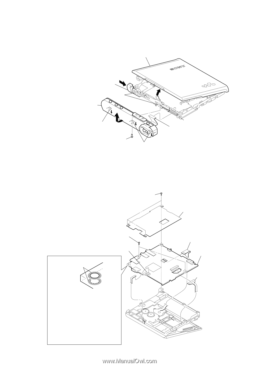
3-3. CABINET (FRONT) SECTION panel (upper) assy MZ-RH1 Ver. 1.1 1 Push the knob (open) in the direction A of arrow A and open the panel (upper) section. convex part of screw hole 5 Remove the cabinet (front) section in the direction of arrow B. 4 Remove from the convex B part of the screw hole. 3 screw (M1.4) convex part of screw hole 2 flexible board (18core) (CN471) 4 Remove from the convex part of the screw hole. 3-4. MAIN BOARD 1 three screws (M1.4) 6 two screws (M1.4) 3 Remove two solders of the flexible board (over write head (HR601)). The screw fixing areas is cleaned. Note: When mounting the MAIN Board, clean the screw fixing areas (5 places × both sides) of the MAIN Board with alcohol (ethanol), and then tighten the screws. Also, when tightening the screws, use a torque driver and tighten them to a torque range of 0.06 - 0.08N. (Excessive torque over 0.1N could bend the chassis.) (Without cleaning, or with the screws tightened loosely, the set may not start when the USB cable is inserted.) 2 shield assy 5 motor flexible board (CN701) 7 MAIN board 4 OP flexible board (CN501) 7
-
 1
1 -
 2
2 -
 3
3 -
 4
4 -
 5
5 -
 6
6 -
 7
7 -
 8
8 -
 9
9 -
 10
10 -
 11
11 -
 12
12 -
13
-
14
-
15
-
16
-
17
-
18
-
19
-
20
-
21
-
22
-
23
-
24
-
25
-
26
-
27
-
28
-
29
-
30
-
31
-
32
-
33
-
34
-
35
-
36
-
37
-
38
-
39
-
40
-
41
-
42
-
43
-
44
-
45
-
46
-
47
-
48
-
49
-
50
-
51
-
52
-
53
-
54
-
55
-
56
-
57
-
58
-
59
-
60
-
61
-
62
-
63
-
64
-
65
-
66
 |
 |