Sony PCWA-DE80 Read This First Operating Instructions - Page 2
Names of Parts and Functions, Installation Precautions, Operating Precautions, Specifications - pcwa de 80
 |
View all Sony PCWA-DE80 manuals
Add to My Manuals
Save this manual to your list of manuals |
Page 2 highlights
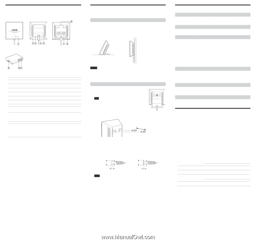
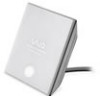
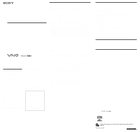
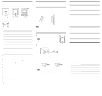
Names of Parts and Functions Wireless Unit Front Rear (With rear cover removed) Power Unit 1 Status indicator Indicates the status of the Wireless LAN Converter. Indicator color and lighting pattern Status White flashing (approx. 9 sec. lit, 1 sec. out) Wireless network connection status: Good (strong signal) White flashing (approx. 5 sec. lit, 1 sec. out) Wireless network connection status: Fair (medium signal) White flashing (approx. 2 sec. lit, 1 sec. out) Wireless network connection status: Poor (weak signal) White flashing (approx. 1 sec. lit, 9 sec. out) Nothing connected to the NETWORK connector or connected devices off. White flashing (approx. half sec. intervals) Startup in progress Wait until startup is complete. White flashing (approx. 0.2 sec. intervals) Wireless LAN Converter quick setup successful with the Quick Setup switch. Pink lit Communicating in Peer to Peer Network connection mode. Red flashing (approx. 6 sec. intervals) Wireless LAN Converter quick setup failed with the Quick Setup switch because it could not acquire setup information from the access point of the PCWA-AR800 or PCWA-AR300. Red flashing (approx. 3 sec. intervals) Search for wireless network in progress Communication is not yet possible because connection is not established. If this condition continues for a long time, check the settings of the Wireless LAN Converter and the connection target (Wireless LAN access point, etc.). Red flashing (approx. 1.6 sec. intervals) Wireless LAN Converter in Quick Setup standby mode. Red flashing (approx. half sec. intervals) • Unit is resetting When you release the reset switch, the Wireless LAN Converter restarts automatically and reverts to its factory default settings. • Firmware update in progress Firmware is being updated. Never turn off the power in this condition. 2 Reset switch Returns Wireless LAN Converter settings to their factory defaults. See the separate Quick Start Guide, Wireless LAN Converter Setup Page Help, or Wireless LAN Converter Setup Utility Help for details. 3 LINK/ACT indicator Lights when an Ethernet cable is connected to the NETWORK connector qa. 4 Wireless Unit cable Connects to the WIRELESS UNIT connector 0 on the Power Unit. 5 Rear cover Remove this cover if you want to hang the Wireless LAN Converter to a wall and to verify the MAC address. See "Hanging the Wireless Unit" for details about removing the rear cover. 6 Wall mounting holes Use these holes to hang the Wireless LAN Converter to a wall. See "Hanging the Wireless Unit" overleaf for details. 7 MAC address label The Wireless LAN Converter MAC address is printed here. 8 Quick Setup switch Use this switch to configure the Wireless LAN Converter with the settings of the Wireless Broadband Router PCWA-AR800 or PCWA-AR300. Refer to the Quick Start Guide of the Wireless LAN Converter for details. 9 100-240 V AC jack Connect the supplied power cord. 0 WIRELESS UNIT connector Connect the Wireless Unit cable 4 here. qa NETWORK connector Connect the Wireless Unit to your computer or other device using an Ethernet cable. z Hint Use a straight-through or crossover Ethernet cable. Installation Precautions Refer to the separate Quick Start Guide for information about connecting the Wireless Unit and Power Unit. Installation Select a secure location for the Wireless Unit where it cannot drop or fall over. Route the cable to the Wireless Unit to suit the installation location. Installation examples • Desktop installation • Hanging Notes • Do not install the Wireless Unit or the Power Unit in insecure locations. • Do not install the Wireless Unit in a location where it may fall as a result of shock or vibrations, such as on the edge of a shelf. • Do not install the Wireless Unit in a location where it or its cables may hinder normal movement. Hanging the Wireless Unit 1 Remove the rear cover of the Wireless Unit by sliding it in the direction of the arrow. Note Be cautious when removing and replacing the rear cover of the Wireless Unit. z Hint To replace the rear cover of the Wireless Unit, align the rails on the rear of the Wireless Unit with the grooves in the rear cover, and slide it upwards. 2 Using screws or nails, hang the unit to a wall. 0.94 (24) Units: in. (mm) The Wireless Unit does not come with any sort of fittings used in hanging it. Use screws or nails of sufficient strength to support it. ■ Recommended screws • Roundhead screws • Flathead screws Ø0.23 (5.7) Ø0.13 (3.1) 0.1 (2.3) Ø0.25 (6.2) Ø0.13 (3.1) 0.08 (1.8) Units: in. (mm) Notes • Always use two screws or nails, and make sure that the Wireless Unit is secure on the wall. • Select a location that will hold the weight of the Wireless Unit when hanging it to a wall. If the selected location cannot hold the weight of the unit, it may fall resulting in damage and/or injury. • When hanging the Wireless Unit to walls of plasterboard or other brittle material, make sure that the material is strong enough to support the Wireless Unit's weight and use special screw fasteners or other fixtures designed for use with the wall material. If the Wireless Unit is hung with ordinary screws or nails, it may fall. • When hanging the Wireless Unit to a wall, be careful not to drop it or the tools used for doing the work. Dropping the Wireless Unit or tools may result in damage and/or injury. Operating Precautions Power Unit Use the Power Unit supplied with the Wireless Unit. Using a different power unit may result in damage and/or injury. Safety Avoid exposing this product to strong impact, as it could result in damage. Installation Do not install the Wireless LAN Converter where it is exposed to the following conditions. • High temperatures (such as direct sunlight and heaters). The operating range of the Wireless LAN Converter is 41ºF to 95ºF (5ºC to 35ºC). • Closed environments (such as closed cars). • Magnetic fields (near magnets, speakers, or televisions). • Microwaves (near microwave ovens). • Excessive dust. • Unstable or uneven surfaces. • Frequent vibration. • High humidity (such as a bathroom). • Poor ventilation. • Locations where the transmission of radio waves may be obstructed by metal plates or concrete walls. Operation Exposure to rapid changes in temperature or very damp environments can cause condensation on internal parts. This may prevent the Wireless LAN Converter from operating normally. If this should happen, disconnect the Wireless LAN Converter from the converter or other device to which it may be connected, and discontinue operation for two to three hours. Cleaning Clean the casing with a soft cloth lightly moistened with water or a mild detergent solution. Do not use any type of abrasive pad, scouring powder, or solvent such as alcohol or benzene. This may damage the finish of the casing. Emergencies In case of an emergency, stop the wireless functions by unplugging the power cord. Specifications Power AC100 - 240 V, 50/60 Hz Power consumption Approx. 5 W Interfaces 100BASE-TX/10BASE-T (RJ-45) (automatic MDI/MDI-X detection) Maximum connection distance Line of sight, approx. 328 ft (100 m) (The actual connection distance depends on the environment.) Supported protocol TCP/IP Standard compliance IEEE 802.11a IEEE 802.11b IEEE 802.11g Radio frequency IEEE 802.11a emits at 5,150 to 5,350 MHz IEEE 802.11b/g emit at 2,400 to 2,483.5 MHz (ISM band) Security WEP 40 or 64 bits 104 or 128 bits ASCII 5 characters (alphanumeric and symbols) 13 characters (alphanumeric and symbols) Hexadecimal 10 characters (0 to 9, A to F, and a to f) 26 characters (0 to 9, A to F, and a to f) WPA-PSK (TKIP or AES) Pre-shared key ASCII 8 to 63 characters (alphanumeric and symbols) Hexadecimal 64 characters (0 to 9, A to F, and a to f) Modulation methods DS-SS OFDM Operating temperature 41°F to 95°F (5°C to 35°C) (temperature gradient less than 18°F (10°C)/hour) Operating humidity 20% to 80% (non condensing), provided that humidity is less than 65% at 95°F (35°C) (hygrometer reading at less than 84°F (29°C)) Storage temperature -4°F to 140°F (-20°C to 60°C) (temperature gradient less than 18°F (10°C)/hour) Storage humidity 10% to 90% (non condensing), provided that humidity is less than 20% at 140°F (60°C) (hygrometer reading at less than 95°F (35°C)). Dimensions Wireless Unit: Power Unit: approx. 4.3 × 1.0 × 2.8 in. (W × H × D) (approx. 110 × 25 × 70 mm) approx. 3.9 × 3.9 × 1.3 in. (W × H × D) (approx. 98 × 98 × 33 mm) Mass Wireless Unit: Power Unit: approx. 9.9 oz. (including connection cable) (approx. 280 g) approx. 4.6 oz. (approx. 130 g) Design and specifications are subject to change without notice.
-
 1
1 -
 2
2
 |
 |