Sony STR-DA4ES Operating Instructions - Page 61
CONTROL A1, S-LINK control system - upgrade
 |
View all Sony STR-DA4ES manuals
Add to My Manuals
Save this manual to your list of manuals |
Page 61 highlights
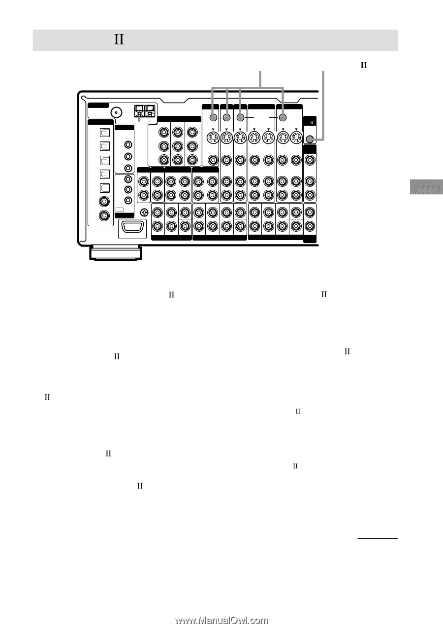
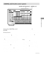
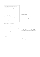
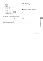
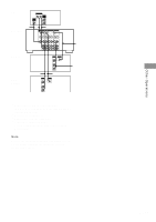
Other Operations CONTROL A1 /S-LINK control system CONTROL (STATUS) IN/OUT CONTROL A1 ANTENNA 75Ω COAXIAL FM DIGITAL CD/SACD OPTICAL IN U IR REMOTE MONITOR TV/SAT DVD/LD VIDEO 2 IN STATUS IN OUT COMPONENT VIDEO CONTROL S AM TV/SAT IN DVD/LD IN MONITOR OUT S2 VIDEO S2 VIDEO S2 VIDEO S2 VIDEO OUT IN IN OUT IN Y VIDEO 1 OUT S2 VIDEO OUT IN CTRL A1 MD/DAT OPTICAL OUT MD/DAT OPTICAL IN TV/SAT OPTICAL IN DVD/LD OPTICAL IN CD/SACD COAXIAL IN DVD/LD COAXIAL IN ASSIGNABLE IR OUT 1 IR OUT 2 PB/CB/B-Y PR/CR/R-Y VIDEO OUT VIDEO IN VIDEO IN VIDEO OUT IN VIDEO OUT IN 2ND ROOM IR IN MAIN ROOM PHONO CD/SACD IN IN L MD/DAT OUT IN TAPE OUT IN AUDIO IN AUDIO IN AUDIO OUT IN AUDIO OUT IN VIDEO OUT AUDIO OUT 2ND ROOM R 3RD ROOM OUT SIGNAL GND FRONT L U TRIGGER SURROUND CENTER FRONT L SURROUND SURR BACK CENTER FRONT L VARIABLE SURROUND SURR BACK CENTER AUDIO OUT R R R RS232C SUB WOOFER MULTI CHANNEL IN 2 SUB WOOFER MULTI CHANNEL IN 1 PRE OUT SUB WOOFER VARIABLE 3RD ROOM Using the CONTROL A1 system Getting Started This section explains the basic functions of the CONTROL A1 Control System. Certain components have special functions, like "CD Synchro Dubbing" on cassette decks, that require CONTROL A1 connections. For detailed information regarding specific operations, be sure to also refer to the Operating Instructions supplied with your component(s). The CONTROL A1 Control System was designed to simplify the operation of audio systems composed of separate Sony components. CONTROL A1 connections provide a path for the transmission of control signals which enable automatic operation and control features usually associated with integrated systems. Currently, CONTROL A1 connections between a Sony CD player, amplifier (receiver), MD deck and cassette deck provide automatic function selection and synchronized recording. In the future, the CONTROL A1 connection will work as a multifunction bus allowing you to control various functions for each component. Notes • The CONTROL A1 Control System is designed to maintain upward compatibility as the Control System is upgraded to handle new functions. In this case, however, older components will not be compatible with the new functions. • Do not operate a 2 way remote control unit when the CONTROL A1 jacks are connected via a PC interface kit to a personal computer running "MD Editor" or similar application. Also, do not operate the connected component in a manner contrary to the functions of the application, as this may cause the application to operate incorrectly. continued 61GB
-
 1
1 -
2
-
3
-
4
-
5
-
6
-
7
-
8
-
9
-
10
-
11
-
12
-
13
-
14
-
15
-
16
-
17
-
18
-
19
-
20
-
21
-
22
-
23
-
24
-
25
-
26
-
27
-
28
-
29
-
30
-
31
-
32
-
33
-
34
-
35
-
36
-
37
-
38
-
39
-
40
-
41
-
42
-
43
-
44
-
45
-
46
-
47
-
48
-
49
-
50
-
51
-
52
-
53
-
54
-
55
-
 56
56 -
 57
57 -
 58
58 -
 59
59 -
 60
60 -
 61
61 -
 62
62 -
 63
63 -
 64
64 -
 65
65 -
 66
66 -
67
-
68
-
69
-
70
-
71
-
72
-
73
-
74
-
75
-
76
-
77
-
78
-
79
-
80
 |
 |