Sony STR-DB940 Operating Instructions - Page 8
Video Component Hookups
 |
View all Sony STR-DB940 manuals
Add to My Manuals
Save this manual to your list of manuals |
Page 8 highlights
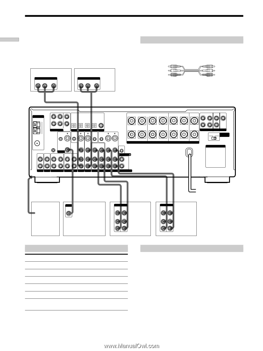
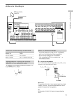
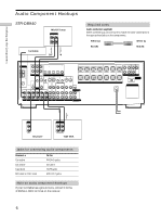
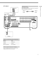
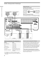
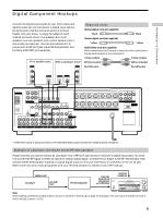
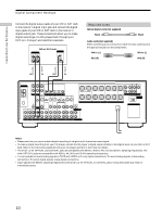
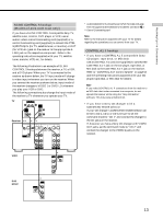
Ç Ç Hooking Up the Components Video Component Hookups TV or satellite tuner OUTPUT AUDIO OUT R L VIDEO OUT DVD or LD player OUTPUT AUDIO OUT R L VIDEO OUT Required cords Audio/video cords (not supplied) When connecting a cord, be sure to match the color-coded pins to the appropriate jacks on the components. Yellow (video) Yellow (video) White (L/audio) White (L/audio) Red (R/audio) Red (R/audio) Video cord for connecting a TV monitor You can use the video cord of the supplied audio/video/control S cord. (Models of area code U, CA only. See page 12 for details). ANTENNA AM L MD/DAT MD/DAT TV/SAT DVD/LD DVD/LD OPTICAL OPTICAL OPTICAL OPTICAL COAXIAL OUT IN IN IN IN CENTER B + U FM 75Ω COAXIAL R FRONT REAR SUB WOOFER 5.1CH INPUT CTRL S IN CTRL S STATUS IN DIGITAL CTRL S OUT CTRL S OUT SIGNAL GND U S-VIDEO OUT VIDEO S-VIDEO S-VIDEO IN IN VIDEO VIDEO OUT VIDEO IN VIDEO S-VIDEO S-VIDEO OUT IN VIDEO VIDEO R - IN L MONITOR IN OUT IN OUT IN AUDIO IN AUDIO IN AUDIO AUDIO OUT IN AUDIO OUT AUDIO IN CONTROL A1 L FRONT A REAR CENTER FRONT REAR SUB WOOFER CENTER L L R L R L SPEAKERS IMPEDANCE USE 4 - 16Ω R PRE OUT IMPEDANCE 4 Ω 8 Ω SELECTOR AC OUTLET R PHONO CD MD/DAT TAPE TV/SAT DVD/LD VIDEO 2 VIDEO 1 R 2ND AUDIO OUT To the front panel OUT IN OUT IN Ç Ç INPUT Camcorder VIDEO IN or video game TV monitor INPUT OUTPUT VIDEO VIDEO IN OUT AUDIO AUDIO IN OUT L R VCR INPUT OUTPUT VIDEO VIDEO IN OUT AUDIO AUDIO IN OUT L R VCR Jacks for connecting video components Connect a TV or satellite tuner VCR Additional VCR DVD or LD player TV monitor1) Camcorder or video game To the TV/SAT jacks VIDEO 1 jacks VIDEO 2 jacks DVD/LD jacks MONITOR VIDEO OUT jack VIDEO 3 INPUT jacks on the front panel 1) For STR-DB940, you can display the SURROUND, LEVEL, EQUALIZER parameters by pressing the ON SCREEN button on the remote. 8 Note on video component hookups You can connect your TV's audio output jacks to the TV/ SAT AUDIO IN jacks on the receiver and apply sound effects to the audio from the TV. In this case, do not connect the TV's video output jack to the TV/SAT VIDEO IN jack on the receiver. If you are connecting a separate TV tuner (or satellite tuner), connect both the audio and video output jacks to the receiver as shown above. z When using the S-video jacks instead of the video jacks Your monitor must also be connected via an S-video jack. S-video signals are on a separate bus from the video signals and will not be output through the video jacks.
-
 1
1 -
2
-
 3
3 -
 4
4 -
 5
5 -
 6
6 -
 7
7 -
 8
8 -
 9
9 -
 10
10 -
 11
11 -
 12
12 -
 13
13 -
14
-
15
-
16
-
17
-
18
-
19
-
20
-
21
-
22
-
23
-
24
-
25
-
26
-
27
-
28
-
29
-
30
-
31
-
32
-
33
-
34
-
35
-
36
-
37
-
38
-
39
-
40
-
41
-
42
-
43
-
44
-
45
-
46
-
47
-
48
-
49
-
50
-
51
-
52
-
53
-
54
-
55
-
56
-
57
-
58
-
59
-
60
-
61
-
62
-
63
-
64
 |
 |