Sony STR-K1600 Service Manual - Page 4

TABLE OF CONTENTS, 20. Printed Wiring Boards - DCAC, Power Key - sw

Page 4 highlights

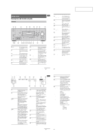
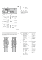
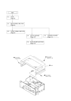
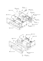
STR-K1600 Ver. 1.1 TABLE OF CONTENTS 1. GENERAL Description and location of parts 5 2. DISASSEMBLY 2-1. Case 8 2-2. Back Panel Section 9 2-3. Front Panel Section 9 2-4. DIGITAL Board 10 2-5. MAIN Board Section 10 2-6. STANDBY Board 11 3. TEST MODE 12 4. FM TUNER CHECK 13 5. DIAGRAMS 5-1. Block Diagram - Tuner/Audio Section 15 5-2. Block Diagram - Digital Section 16 5-3. Block Diagram - Video Section 17 5-4. Block Diagram - HDMI SW Section 18 5-5. Block Diagram - Key/Display Section 19 5-6. Block Diagram - Power Section 20 5-7. Printed Wiring Boards - Main Section 22 5-8. Schematic Diagram - Main Section (1/2 23 5-9. Schematic Diagram - Main Section (2/2 24 5-10. Printed Wiring Board - Digital Section (1/2 25 5-11. Printed Wiring Board - Digital Section (2/2 26 5-12. Schematic Diagram - Digital Section (1/4 27 5-13. Schematic Diagram - Digital Section (2/4 28 5-14. Schematic Diagram - Digital Section (3/4 29 5-15. Schematic Diagram - Digital Section (4/4 30 5-16. Printed Wiring Boards - Video Section 31 5-17. Schematic Diagram - Video Section 32 5-18. Printed Wiring Board - HDMI SW Section 33 5-19. Schematic Diagram - HDMI SW Section 34 5-20. Printed Wiring Boards - DCAC, Power Key Section - .... 35 5-21. Schematic Diagram - DCAC, Power Key Section - ........ 35 5-22. Printed Wiring Board - Display Section 36 5-23. Schematic Diagram - Display Section 37 5-24. Printed Wiring Board - Power Section 38 5-25. Schematic Diagram - Power Section 39 5-26. Printed Wiring Board - DCDC Section (AUS, MY, SP, TH model 40 5-27. Schematic Diagram - DCDC Section (AUS, MY, SP, TH model 40 6. EXPLODED VIEWS 6-1. Case Section 49 6-2. Front Panel Section 50 6-3. Back Panel Section 51 6-4. Chassis Section 52 7. ELECTRICAL PARTS LIST 53 4

  • 1
  • 2
  • 3
  • 4
  • 5
  • 6
  • 7
  • 8
  • 9
  • 10
  • 11
  • 12
  • 13
  • 14
  • 15
  • 16
  • 17
  • 18
  • 19
  • 20
  • 21
  • 22
  • 23
  • 24
  • 25
  • 26
  • 27
  • 28
  • 29
  • 30
  • 31
  • 32
  • 33
  • 34
  • 35
  • 36
  • 37
  • 38
  • 39
  • 40
  • 41
  • 42
  • 43
  • 44
  • 45
  • 46
  • 47
  • 48
  • 49
  • 50
  • 51
  • 52
  • 53
  • 54
  • 55
  • 56
  • 57
  • 58
  • 59
  • 60
  • 61
  • 62
  • 63
  • 64
  • 65
  • 66
  • 67
  • 68

4
STR-K1600
TABLE OF CONTENTS
1. GENERAL
Description and location of parts
.............................................
5
2. DISASSEMBLY
2-1.
Case
.....................................................................................
8
2-2.
Back Panel Section
..............................................................
9
2-3.
Front Panel Section
.............................................................
9
2-4.
DIGITAL Board
................................................................
10
2-5.
MAIN Board Section
........................................................
10
2-6.
STANDBY Board
.............................................................
11
3. TEST MODE
.....................................................................
12
4. FM TUNER CHECK
.......................................................
13
5. DIAGRAMS
5-1.
Block Diagram – Tuner/Audio Section –
..........................
15
5-2.
Block Diagram – Digital Section –
...................................
16
5-3.
Block Diagram – Video Section –
.....................................
17
5-4.
Block Diagram – HDMI SW Section –
.............................
18
5-5.
Block Diagram – Key/Display Section –
..........................
19
5-6.
Block Diagram – Power Section –
....................................
20
5-7.
Printed Wiring Boards – Main Section –
..........................
22
5-8.
Schematic Diagram – Main Section (1/2) –
......................
23
5-9.
Schematic Diagram – Main Section (2/2) –
......................
24
5-10. Printed Wiring Board – Digital Section (1/2) –
................
25
5-11. Printed Wiring Board – Digital Section (2/2) –
................
26
5-12. Schematic Diagram – Digital Section (1/4) –
...................
27
5-13. Schematic Diagram – Digital Section (2/4) –
...................
28
5-14. Schematic Diagram – Digital Section (3/4) –
...................
29
5-15. Schematic Diagram – Digital Section (4/4) –
...................
30
5-16. Printed Wiring Boards – Video Section –
.........................
31
5-17. Schematic Diagram – Video Section –
..............................
32
5-18. Printed Wiring Board – HDMI SW Section –
...................
33
5-19. Schematic Diagram – HDMI SW Section –
.....................
34
5-20. Printed Wiring Boards – DCAC, Power Key Section –
....
35
5-21. Schematic Diagram – DCAC, Power Key Section –
........
35
5-22. Printed Wiring Board – Display Section –
........................
36
5-23. Schematic Diagram – Display Section –
...........................
37
5-24. Printed Wiring Board – Power Section –
..........................
38
5-25. Schematic Diagram – Power Section –
.............................
39
5-26. Printed Wiring Board
– DCDC Section (AUS, MY, SP, TH model) –
.................
40
5-27. Schematic Diagram
– DCDC Section (AUS, MY, SP, TH model) –
.................
40
6. EXPLODED VIEWS
6-1.
Case Section
......................................................................
49
6-2.
Front Panel Section
...........................................................
50
6-3.
Back Panel Section
............................................................
51
6-4.
Chassis Section
.................................................................
52
7. ELECTRICAL PARTS LIST
........................................
53
Ver. 1.1