Sony STR-ZA5000ES Help Guide Printable PDF - Page 7
Power indicator, Indicators on the display panel
 |
View all Sony STR-ZA5000ES manuals
Add to My Manuals
Save this manual to your list of manuals |
Page 7 highlights
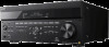
3. Input buttons Select the device you want to use. 4. TONE MODE, TONE+/- Press to adjust the bass/treble level of the speaker. 5. SPEAKERS Select the front speaker system (FRONT A speakers, FRONT B speakers or both FRONT A and FRONT B speakers) or turn off the speaker output. 6. AUTO CAL MIC jack Connect the supplied optimizer microphone for Auto Calibration to this jack. 7. HDMI OUT Switches the output for two monitors connected to the HDMI OUT A and HDMI OUT B (ZONE 2) jacks. 8. SETTING (USB) port Used for maintenance and service. 9. ZONE CONTROL (ZONE2, ZONE3) Selects the place where you will control. 10. MEMORY Press to store a station during tuner operation. 11. CUSTOM PRESET (1, 2, 3, 4) Saves and recalls various settings for the receiver. 12. TUNING MODE, TUNING +/- Press to operate a tuner (FM/AM). 13. DISPLAY Displays information on the display panel. 14. RETURN Returns to the previous menu. 15. HOME Displays the home menu on the TV screen. 16. ENTER, / / / Press / / / to select the menu items. Then press ENTER to enter the selection. 17. OPTIONS Displays and selects items from the options menus. 18. AMP MENU Displays the menu on the display panel of the receiver to operate the receiver. 19. IN-CEILING SP Activates the In-Ceiling Speaker Mode. 20. SOUND FIELD (2CH/DIRECT, A.F.D., MOVIE, MULTI ST.) Selects the sound field you want. 21. HDMI IN 6 (GAME) jack Connect to a video game console. The video and sound from your video game console is input. [3] Parts and Controls Receiver Power indicator Green: The receiver is turned on. Amber: The receiver is in standby mode, and: [Control for HDMI] or [Network Standby] is set to [On]. [Pass Through] is set to [On] or [Auto]. [Zone2 Power] or [Zone3 Power] is set to [On]. The indicator turns off when the receiver is in standby mode and [Control for HDMI], [Pass Through], [Network Standby], [Zone2 Power] and [Zone3 Power] are set to [Off]. The top of the cabinet may become hot. This is because part of the circuit(s) inside the receiver is(are) still turned on, and is not a malfunction. Note The indicator flashes slowly when a software update is in progress. [4] Parts and Controls Receiver Indicators on the display panel
-
 1
1 -
 2
2 -
 3
3 -
 4
4 -
 5
5 -
 6
6 -
 7
7 -
 8
8 -
 9
9 -
 10
10 -
 11
11 -
 12
12 -
13
-
14
-
15
-
16
-
17
-
18
-
19
-
20
-
21
-
22
-
23
-
24
-
25
-
26
-
27
-
28
-
29
-
30
-
31
-
32
-
33
-
34
-
35
-
36
-
37
-
38
-
39
-
40
-
41
-
42
-
43
-
44
-
45
-
46
-
47
-
48
-
49
-
50
-
51
-
52
-
53
-
54
-
55
-
56
-
57
-
58
-
59
-
60
-
61
-
62
-
63
-
64
-
65
-
66
-
67
-
68
-
69
-
70
-
71
-
72
-
73
-
74
-
75
-
76
-
77
-
78
-
79
-
80
-
81
-
82
-
83
-
84
-
85
-
86
-
87
-
88
-
89
-
90
-
91
-
92
-
93
-
94
-
95
-
96
-
97
-
98
-
99
-
100
-
101
-
102
-
103
-
104
-
105
-
106
-
107
-
108
-
109
-
110
-
111
-
112
-
113
-
114
-
115
-
116
-
117
-
118
 |
 |
