Sony TC-WR720A Service Manual - Page 8
Tc-wr720/wr720a, Mechanical, Adjustments, Electrical
 |
View all Sony TC-WR720A manuals
Add to My Manuals
Save this manual to your list of manuals |
Page 8 highlights
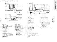
TC-WR720/WR720A SECTION 3 MECHANICAL ADJUSTMENTS PRECAUTION 1. Clean the following parts with a denatured alcohol- moistened swab : record/playback head pinch roller erase head rubber belts capstan idlers 2. Demagnetize the record/playback head with a head demagnetizer. (Head demagnetizer do not approach for the erase head.) 3. Do not use a magnetized screwdriver for the adjustment. 4. After the adjustments, apply suitable locking compound to the parts adjusted. 5. The adjustments should be perfomed with the rated power supply voltage unless otherwise noted. Torque Measurement Torque Torque meter Forward CQ-102C Forward back tension CQ-102C Reverse CQ-102RC Reverse back tension Forward, Reverse CQ-102RC CQ-201B Meter reading 30 to 65g-cm (0.42 to 0.90 oz•inch) 1 to 6g-cm (0.014 to 0.08 oz•inch) 30 to 65g-cm (0.42 to 0.90 oz•inch) 1 to 6g-cm (0.014 to 0.08 oz-inch) 70 to 120g-cm (0.98 to 1.67 oz•inch) TP1 2 1 short SECTION 4 ELECTRICAL ADJUSTMENTS PRECAUTION 1. The adjustment should be performed in the publication. (Be sure to make playback adjustment at first.) 2. The adjustment and measurement should be performed for both L-CH and R-CH. • Switch position DOLBY NR switch : OFF DIR MODE switch : = • Standard record position Deliver the standard input signal level to input jack and set the REC LEVEL control to obtain the standard output signal level as follows. -Record Mode- AF OSC VTVM 0 attenuator 10k0 O--I-° OO O set 6000 LINE IN 47k0 LINE OUT Standard Input Level Input terminal source impedance input signal level LINE IN 10kil 0.25V (-10dB) Standard Output Level Output terminal load impedance output signal level LINE OUT 47kS2 0.44V (-5dB) Test Tape Tape P-4-A100 P-4-L300 WS-48B Contents 10kHz, -10dB 315Hz, 0dB 3kHz, 0dB Use Azimuth Adjustment Level Adjustment Tape Speed Adjustment 3. Perior to electrical adjustments, short the connector TP1 (test mode). audio system control board --component side- C712 O C708 O Q707 O0 IC805 IC802 IC803 RV221 BRV121 RV222 BRV122
-
 1
1 -
2
-
 3
3 -
 4
4 -
 5
5 -
 6
6 -
 7
7 -
 8
8 -
 9
9 -
 10
10 -
 11
11 -
 12
12 -
 13
13 -
14
-
15
-
16
-
17
-
18
-
19
-
20
-
21
-
22
-
23
-
24
-
25
-
26
-
27
-
28
-
29
-
30
-
31
-
32
 |
 |
