Sony VGC-RB40 VGC-RBxx Series Optical Disk Drive Lower Replacement Instruction - Page 1
Sony VGC-RB40 - Vaio Desktop Computer Manual
 |
View all Sony VGC-RB40 manuals
Add to My Manuals
Save this manual to your list of manuals |
Page 1 highlights
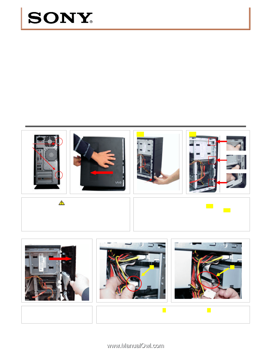
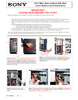
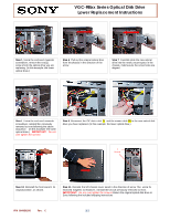
VGC-RBxx Series Optical Disk Drive Lower Replacement Instructions IMPORTANT! PLEASE READ BEFORE YOU START These easy instructions are intended to guide you through the replacement process. ü To avoid electric shock please make sure product is turned off and disconnected from the power source. Remove jewelry before you begin work to avoid scratching the surface of your desktop computer.* ü Place your desktop computer on a clean, stable and covered surface to avoid damage to the computer's case.* ü Follow the ESD (Electrostatic Discharge) damage prevention instructions: o Hold parts by the edges, away from exposed circuitry when possible. o Do not walk around excessively as this promotes static build-up. ü The appearance of the electronic components shown in the illustrations may be different from the components shipped. This slight difference does not affect the accuracy of these instructions. * Sony is not responsible for any loss of data associated with your computer or any damage caused by incorrect handling of the computer under these procedures. The terms of your Sony Limited Wa rranty continue to apply. 2 Screws [2A] [2B] Step 1. CAUTION! Disconnect the power cord. Failure to do so can result in damage to the PC or personal injury. Using the enclosed magnetic screwdriver, remove the t w o (2) indicated screws, loosening the chassis panel cover. Rotate the unit so the panel with the vents is facing you. Remove the panel and set it aside. Pull two (2) clips at the bottom of unit. Inside View Step 2. Loosen the front panel cover by pulling down thet w o(2) black clips on the bottom of the unit: Step [2A], and the three (3) black clips on the inside of the front of the unit: Step [2B], as indicated above. [1] [2] Step 3. Carefully remove the front panel in the direction of arrow and s et aside. Step 4. Remove the power connector [1] and the IDE data cable [ 2] from the optical disk drive you are replacing. (In this example: the lower optical drive.) NOTE! Your PC may be equipped with more than one optical disk drive. P/N 994630200 Rev. C 1/2
-
 1
1 -
 2
2
 |
 |