Sony VGC-RB40 VGC-RBxx Series Optical Disk Drive Upper Replacement Instruction - Page 2
VGC-RBxx Series Optical Disk Drive, Upper Replacement Instructions - g series
 |
View all Sony VGC-RB40 manuals
Add to My Manuals
Save this manual to your list of manuals |
Page 2 highlights
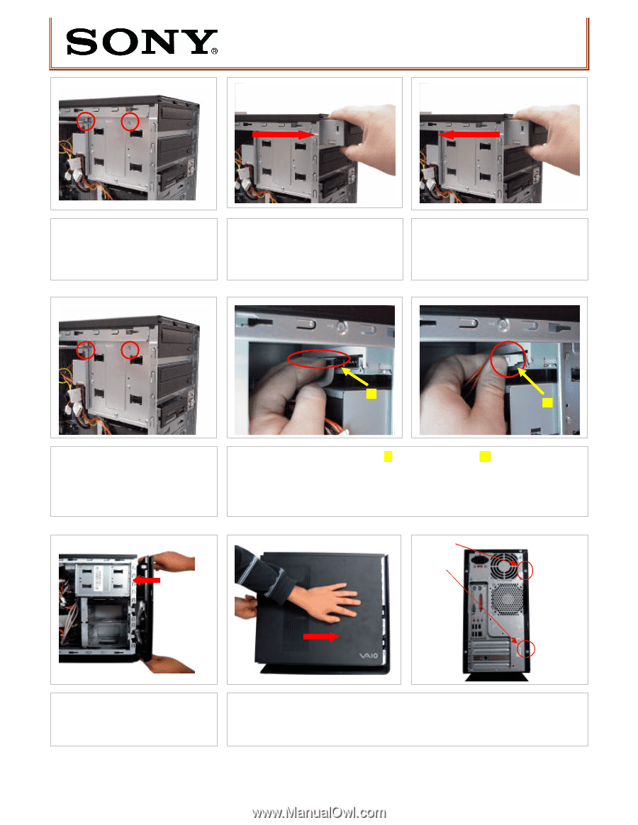
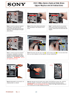
VGC-RBxx Series Optical Disk Drive Upper Replacement Instructions Step 5. Using the enclosed magnetic screwdriver, remove the two (2) screw s from the optical drive you are rep lacing. (In this example: the upper optical drive.) Step 6. Pull out the original optical drive from the chassis in the direction of the arrow. Step 7. Carefully slide the new optical drive into the newly vacant space in the chassis, making sure the screw holes are aligned. 2 1 [1] [2] Step 8. Using the enclosed magnetic screwdriver, reinstall the previously removed screwsfollowing the above sequence. ( In this example: the upper optical drive.) IMPORTANT! Do not over tighten the screws! Step 9. Reconnect the IDE data cable [ 1] and the power cable [2] to the new optical disk drive you have replaced. (In this example: the lower optical drive.) 2 Screws Step 10. Reinstall the front panel to its original position , as shown. Step 11. Reinstall the left chassis cover panel in the direction of arrow.Then using the enclosed magnetic screwdriver, reinstall the two (2) previously removed screws. IMPORTANT! Do not over tighten the screw s! Return the original optical disk drive to Sony following the included shipping instructions P/N 994630100 Rev. C 2/2
-
 1
1 -
 2
2
 |
 |