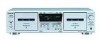
Sony WE475 Service Manual - Page 8
Tc-we475, Electrical Adjustments, Mechanical Adjustments - tape deck tc
 |
UPC - 027242584419
View all Sony WE475 manuals
Add to My Manuals
Save this manual to your list of manuals |
Page 8 highlights
TC-WE475 SECTION 4 MECHANICAL ADJUSTMENTS PRECAUTION 1. Clean the following parts with a denatured alcohol-moistened swab : record/playback/erase head pinch roller rubber belts capstan idlers 2. Demagnetize the record/playback head with a head demagne- tizer. 3. Do not use a magnetized screwdriver for the adjustment. 4. After the adjustments, apply suitable locking compound to the parts adjusted. 5. The adjustments should be performed with the rated power sup- ply voltage unless otherwise noted. Torque Measurement Mode Forward Torque meter CQ-102C Forward back tension CQ-102C Reverse Reverse back tension FF/REW CQ-102RC CQ-102RC CQ-201B Meter reading 30 to 65 g • cm (0.42 to 0.90 oz • inch) DECK A : 1 to 6 g • cm (0.014 to 0.083 oz • inch) DECK B : 2 to 9 g • cm (0.028 to 0.125 oz • inch) 30 to 65 g • cm (0.42 to 0.90 oz • inch) 1 to 6 g • cm (0.014 to 0.083 oz • inch) 70 to 120 g • cm (0.97 to 1.67 oz • inch) SECTION 5 ELECTRICAL ADJUSTMENTS PRECAUTION 1. The adjustment should be performed in the publication. (Be sure to male playback adjustment at first.) 2. The adjustments and measurement should be performed for both L-CH and R-CH. • Switch position DOLBY NR switch : OFF DIRECTION MODE switch : g • Standard record position : Deliver the standard input signal level to input jack and set the REC LEVEL knob to obtain the standard output signal level as follows. - Record Mode- AF OSC attenuator 10 kΩ 600 Ω LINE IN level meter 47 kΩ + set - LINE OUT Standard Input Level Input terminal source impedance input signal level LINE IN 10 kΩ 0.5 V (-3.8 dBs) Standard Output Level Input terminal source impedance input signal level LINE IN 10 kΩ 0.5 V (-3.8 dBs) Test Tape Tape P-4-A100 WS-48B P-4-L300 Contents 10 kHz, -10 dB 3 kHz, 0 dB 315 Hz, 0 dB 0 dBs = 0.775 V Use Azimuth Adjustment Tape Speed Adjustment PB Level Adjustment Test Mode 1. While pressing the H (DECK A) and REC MUTING W buttons with the power off, press the ! button to turn on the power. The fluorescent display tube lights up for about one second, and the test mode is set. The test mode performs the following two special functions. • Playback speed switching function Pressing the HIGH/NORMAL button switches the playback speed between standard/double speed. • Counter RESET & MEMORY function Resets the counter when recording starts. When rewound with the m (AMS) button after recording, stops at the point where recording started. 2. To release the test mode, turn OFF the power switch. 8
-
 1
1 -
2
-
 3
3 -
 4
4 -
 5
5 -
 6
6 -
 7
7 -
 8
8 -
 9
9 -
 10
10 -
 11
11 -
 12
12 -
 13
13 -
14
-
15
-
16
-
17
-
18
-
19
-
20
-
21
-
22
-
23
-
24
-
25
-
26
-
27
-
28
-
29
-
30
-
31
-
32
-
33
-
34
-
35
-
36
-
37
-
38
 |
 |
