Sony XCDSX90 User Manual (XCDV60_V60CR_SX90_SX90CR_U100_U100CR_Operating_Instr - Page 2
About the Technical Manual - xcd sx90 software
 |
View all Sony XCDSX90 manuals
Add to My Manuals
Save this manual to your list of manuals |
Page 2 highlights
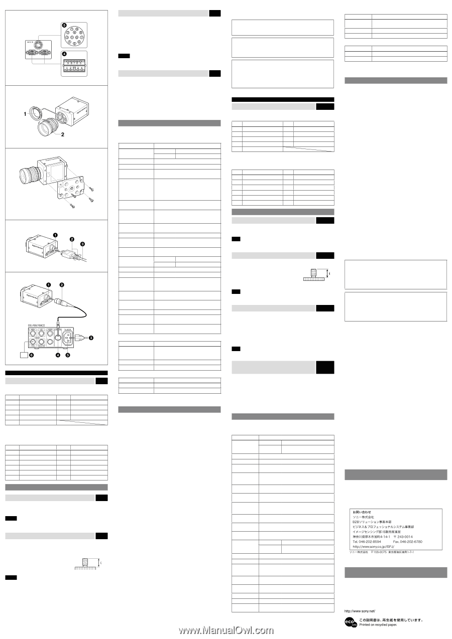
日本語 ޙ໘ ਤD IEEE1394b IEEE1394b ピン番号 信号 ピン番号 信号 1 TPBʵ 6 VG 2 TPBʴ 7 NC 3 TPAʵ 8 VP 4 TPAʴ 9 TPBG 5 TPAG 12ピンI/O IEEE1394b CCXC-12P05N ピン番号 信号 ピン番号 信号 1 7 GPIOೖྗ2 2 8 GPIOग़ྗ2ʵ 3 ISO(Ξʔε) 9 GPIOग़ྗ2ʴ 4 10 GPIOೖྗ1 5 GPIOग़ྗ1ʵ 11 6 GPIOग़ྗ1ʴ 12 ISO(Ξʔε) ઃஔ ਤE 1 2 ご注意 ਤF VCT-ST70I ISO 4.5mm ʙ 5.0mm ASA 0.197Πϯν ご注意 ਤG ࢢൢͷIEEE1394b IEEE1394b 1394bΠ IEEE1394bࢠ IEEE1394b ご注意 IEEE1394b H IEEE1394b DC700 CCXC-12P05N 12ϐϯI/O CCXC-12P05NͳͲʣ AC CAMERA AC INࢠ τϦΨʔ GPIO ISO Enable OneShot/MultiShot DataDepth CameraInitialize 1394 όϧΫϞʔυ 内容 0 ʙ +18 dB 0 ʙ +24 dB /1 100,000 ʙ 16ඵʹՄม 1024 10 IIDC Mode0 Mode1 12 GPIO OneShot ը૾1ຕΛసૹ MultiShot 16 PresetMemory0 1 ch/15 ch ೳ 1394 32ϥΠϯ x 24 256 උ XCD-V60CR/SX90CR/U100CR 制御項目 内容 Raw RɺB Ϟʔυʣ ϥϯε GήΠϯ G XCD-V60/SX90/U100 制御項目 内容 3 x 3ϑΟϧλʔ 3 x 3 γϟʔϓωε IEEE1394 Ver.1.31 ओͳ༷ ࡱ૾ૉࢠ IT CCD XCD-V60CR/V60/SX90CR/SX90: 1/3ܕ XCD-U100CR/U100: 1/1.8ܕ IEEE1394b - 2002 XCD-V60CR/V60: 640 x 480 (VGA) XCD-SX90CR/SX90: 1,280 x 960 (SXGA) XCD-U100CR/U100: 1,600 x 1,200 (UXGA) XCD-V60CR/V60: 90 fps XCD-SX90CR/SX90: 30 fps XCD-U100CR/U100: 15 fps సૹ 800/400 Mbps ύϧε෯ɿ10 ЖsҎ্ ৼ෯ɿDC 5 ʙ 24V CϚϯτ 17.526 mm XCD-V60CR/SX90CR/U100CR: 20 lx (F1.4 Gain: +18 dB) XCD-V60/SX90/U100: 2 lx (F1.4 Gain: +24 dB) ΨϯϚ Ѝ= 1ʢLUTͰઃఆՄʣ ήΠϯ XCD-V60CR/SX90CR/U100CR: 0 ʙ +18 dBɺΦʔ τήΠϯ XCD-V60/SX90/U100: 0 ʙ +24 dBɺΦʔτήΠ ϯ 1/100,000 ʙ 16 ిݯ IEEE1394b 12ϐϯίωΫ DC +8 V ʙ +30 V Λڅڙ ফඅిྗ XCD-V60CR/V60/SX90CR/SX90: 2.8 WʢDC 12V ೖྗ࣌ʣ XCD-U100CR/U100: 3.0 WʢDC 12Vೖྗ࣌ʣ 0 ʙ +40ˆ ಈ࡞Թ ʵ5ʙʴ45ˆ อଘԹ ʵ30ʙʴ60ˆ ༻࣪ 20ʙ80 อଘ࣪ 20ʙ95 ৼಈੑ 10G (20Hzʙ200Hz িܸੑ 70G 44 (W)ʷ33 (H)ʷ57.5 (D)mm ॏྔ 140g ଐ 1) 1) VCCI A English Rear Fig. D IEEE1394b connectors Connect an IEEE1394b camera cable (not supplied) to this connector. Pin No. Signal Pin No. Signal 1 TPB- 6 VG 2 TPB+ 7 NC 3 TPA- 8 VP 4 TPA+ 9 TPBG 5 TPAG 12-pin I/O connector When power from the IEEE1394b connector is insufficient, power is supplied through this connector. Connect a camera cable such as the CCXC-12P05N to this connector. Pin No. Signal Pin No. Signal 1 Power GND 7 GPIO IN 2 2 Power IN 8 GPIO OUT 2- 3 ISO GND 9 GPIO OUT 2+ 4 Strobe OUT 10 GPIO IN 1 5 GPIO OUT 1- 11 Trigger IN 6 GPIO OUT 1+ 12 ISO GND Installation Fitting the lens Fig. E 1 Remove the lens mount cap. 2 Screw in the lens (not supplied), and turn it until it is secured. Note Clean the optical filter with a commercially available blower brush to remove dust. Using a tripod Fig. F To use the tripod, install the VCT-ST70I tripod adaptor (not supplied) on the camera module. Use a tripod screw with a protrusion () extending from the installation surface, as follows: ISO standard: Length 4.5 mm to 5.0 mm ASA standard: Length 0.197 inches Tighten the tripod screws using a hand screwdriver. Note When you install the tripod adaptor, use the screws supplied with the tripod adaptor. Connecting the camera cable Fig. G Connect a commercially available IEEE1394b camera cable to the IEEE1394b connector and the 1394b interface connector of your PC. When you connect the cable, insert the cable connector into the IEEE1394b connector until it snaps into place, holding it. Then, tighten the fixing screws placed on both sides of the cable connector. IEEE1394b connector Fixing screws IEEE1394b camera cable (not supplied) Note Loose fixing screws may cause a poor connection or damage to the camera or cable. Be sure to tighten the fixing screws. When power supply from the IEEE1394b connector is insufficient Fig. H Power can be supplied to the camera module via the DC-700/700CE camera adaptor (optional) and a camera cable such as CCXC-12P05N (optional) if power supply from the IEEE1394b connector is insufficient. 12-pin I/O connector Camera cable (e.g. CCXC-12P05N) to AC power source CAMERA connector AC IN connector Trigger generator Controlling the Camera from Your PC You can control the camera from your PC. The following table shows the control functions. Functions common to all models Control function Description Gain Color model 0 to +18 dB Black and white model 0 to +24 dB Shutter Setting the shutter speed between 1/100,000 and 16 sec. Brightness Pedestal level adjustable Gamma Customizing the gamma curve using 1,024 gamma tables (10 bits) (IIDC extended function) Trigger Mode 0 (control by register) and Mode 1 (control by pulse width) supported for hardware trigger/software trigger Broadcast commands supported for software trigger Strobe Out Setting the delay from the exposure start and the pulse width by register value AutoExposure Keeping a constant average image level by the image level detection and feedback to gain and shutter AutoExposure Detection Frame Setting Setting the detection area for Auto Exposure GPIO Assigning GPIO (General-Purpose Input/Output) to the 12-pin connector MemoryShot Saving an image to the built-in frame memory and reading the saved image from the memory ISO Enable (Video Start) Starts transmitting an image in continuous mode OneShot/ MultiShot OneShot MultiShot Transmitting an image Transmitting the specified number of images DataDepth Indicating the effective bit length in 16-bit mode CameraInitialize Resetting the camera to the default features MemoryChannel PresetMemory0 (factory default status) and 1 user available memory channel / 15 user available memory channels selectable 1394 Bus Defining the exposure timing in synchronization with Synchronization the cycle time register of 1394 bus TriggerDelay Specifying the delay time after which the received trigger becomes effective PartialScan Partition by a unit of 32 lines x 24 pixels available UserFreeMemory A 256-byte user available memory provided Bulk Mode Acquiring images continuously by changing the settings in memory channels XCD-V60CR/SX90CR/U100CR (color models) only Control function Description WhiteBalance (Raw Adjusting the R and B levels individually mode) Auto white balance, One Push white balance available G Gain Adjusting the G gain OpticalFilter Switching the Bayer pattern XCD-V60/SX90/U100 (black and white models) only Control function Description 3 x 3 Filter Switching the 3 x 3 filter Sharpness Adjusting the image contour strength These control items comply with Digital Camera Protocol, Ver. 1.31, of the IEEE1394 Standard. For more details, refer to the Technical Manual. Specifications Pickup device Progressive scan IT CCD XCD-V60CR/V60/SX90CR/SX90: 1/3 type XCD-U100CR/U100: 1/1.8 type Interface IEEE1394b - 2002 Output signal format (horizontal/vertical) XCD-V60CR/V60: 640 x 480 (VGA) XCD-SX90CR/SX90: 1,280 x 960 (SXGA) XCD-U100CR/U100: 1,600 x 1,200 (UXGA) Frame rate XCD-V60CR/V60: 90 fps XCD-SX90CR/SX90: 30 fps XCD-U100CR/U100: 15 fps Transfer speed 800/400 Mbps External trigger signal (conditions) Pulse width: 10 μs or more Polarity: Negative Amplitude: 5 to 24 V DC Lens mount C-mount Flange back 17.526 mm Minimum illumination XCD-V60CR/SX90CR/U100CR: 20 lx (F1.4, Gain: +18 dB) XCD-V60/SX90/U100: 2 lx (F1.4, Gain: +24 dB) Gamma γ= 1 (selectable by LUT) Gain XCD-V60CR/SX90CR/U100CR: 0 to +18 dB, Auto gain XCD-V60/SX90/U100: 0 to +24 dB, Auto gain Shutter speed 1/100,000~16 seconds, Auto shutter Power +8 V to +30 V DC from IEEE1394b camera cable or camera cable with 12-pin connector Power consumption XCD-V60CR/V60/SX90CR/SX90: 2.8 W (12 V DC input) XCD-U100CR/U100: 3.0 W (12 V DC input) Performance guaranty temperature 0 to +40°C (32 to 104°F) Operating temperature -5 to +45°C (23 to 113°F) Storage temperature -30 to +60°C (-22 to 140°F) Operating relative humidity 20 to 80% (no condensation) Storage relative humidity 20 to 95% (no condensation) Vibration resistance 10 G (20 Hz to 200 Hz, at using the reference holes) Shock resistance 70 G External dimension (w/h/d) 44 × 33 × 57.5 mm (13/4 × 13/16 × 23/8 inches), not including projecting parts Mass 140 g (4 oz) Accessories Lens mount cap (1) Operating Instructions (1) Design and specifications are subject to change without notice. IMPORTANT The nameplate is located on the bottom. Note Always verify that the unit is operating properly before use. SONY WILL NOT BE LIABLE FOR DAMAGES OF ANY KIND INCLUDING, BUT NOT LIMITED TO, COMPENSATION OR REIMBURSEMENT ON ACCOUNT OF THE LOSS OF PRESENT OR PROSPECTIVE PROFITS DUE TO FAILURE OF THIS UNIT, EITHER DURING THE WARRANTY PERIOD OR AFTER EXPIRATION OF THE WARRANTY, OR FOR ANY OTHER REASON WHATSOEVER. Regular parts replacement Some of the parts that make up this product (electrolytic condenser, for example) need replacing regularly depending on their life expectancies. The lives of parts differ according to the environment or condition in which this product is used and the length of time it is used, so we recommend regular checks. Consult the dealer from whom you bought it for details. About the Technical Manual The Operating Instructions describe the functions and use of this product. For more details, see the Technical Manual. Please ask your sales representative about the Technical Manual.
-
 1
1 -
 2
2
 |
 |