Sony XCDSX90CR User Manual (XCDV60_V60CR_SX90_SX90CR_U100_U100CR_Operating_Ins - Page 1
Sony XCDSX90CR Manual
 |
View all Sony XCDSX90CR manuals
Add to My Manuals
Save this manual to your list of manuals |
Page 1 highlights
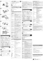
3-287-508-01 (1) Digital Camera Module Owner's Record The model and serial numbers are located on the bottom. Record the serial number in the space provided below. Refer to these numbers whenever you call upon your Sony dealer regarding this product. Model No Serial No Operating Instructions XCD-V60CR/SX90CR/U100CR (Color model) XCD-V60/SX90/U100 (Black and white model) 2007 Sony Corporation Printed in Japan 3287508010 ͋Γ·͢ɻ WARNING To reduce the risk of fire or electric shock, do not expose this apparatus to rain or moisture. To avoid electrical shock, do not open the cabinet. Refer servicing to qualified personnel only. IMPORTANT The nameplate is located on the bottom. Power Supply The unit must always be operated with a 12V DC class 2 power supply. In the USA, use a power supply which is UL Listed. For the customers in the U.S.A. This equipment has been tested and found to comply with the limits for a Class A digital device, pursuant to Part 15 of the FCC Rules. These limits are designed to provide reasonable protection against harmful interference when the equipment is operated in a commercial environment. This equipment generates, uses, and can radiate radio frequency energy and, if not installed and used in accordance with the instruction manual, may cause harmful interference to radio communications. Operation of this equipment in a residential area is likely to cause harmful interference in which case the user will be required to correct the interference at his own expense. You are cautioned that any changes or modifications not expressly approved in this manual could void your authority to operate this equipment. All interface cables used to connect peripherals must be shielded in order to comply with the limits for a digital device pursuant to Subpart B of Part 15 of FCC Rules. For customers in Europe This camera is not intended for use in security applications in the meaning of the European standard series EN 50132 (Alarm systems CCTV surveillance systems for use in security applications). For the customers in Europe The manufacturer of this product is Sony Corporation, 1-7-1 Konan, Minato-ku, Tokyo, Japan. The Authorized Representative for EMC and product safety is Sony Deutschland GmbH, Hedelfinger Strasse 61, 70327 Stuttgart, Germany. For any service or guarantee matters please refer to the addresses given in separate service or guarantee documents. This apparatus shall not be used in the residential area. ·ͨɺ1 ·ͨɺ1 -1 Χϝϥ / Camera -2 Χϝϥ / Camera DC 日本語 ਤA -1 2 IEEE1394b PCͳͲʣ 12ϐϯI/O DC-700ʣ PC͔ΒIEEE1394b DC-700 0ʙ40ˆͰ͢ɻ お手入れ ओͳಛ XCD-V60CR/SX90CR/U100CRRAW XCD-V60/SX90/U100 IEEE1394b端子 సૹ800Mbps IEEE1394bࢠΛ2ͭࡌ͢Δ CCD ·͢ɻ XCD-V60CR/V60ɺVGAରԠͷ33ສըૉCCDʹΑΓຖඵ90 XCD-SX90CR/SX90ɺSXGAରԠͷ125ສըૉCCD 30 XCD-U100CR/U100ɺ UXGAରԠͷ200ສըૉCCDʹΑΓຖඵ15 CCD 12ピンI/O IEEE1394b 12 12 I/O XCD-V60CR/V60/SX90CR/SX90 2.8WʢDC 12V XCD-U100CR/U100Ͱ3.0WʢDC 12V CCD CCD CCD Charge Coupled Deviceʣ 白点 CCD ͜ΕCCD ߏ ਤB CCD IEEE1394b IEEE1394b C PCͳͲʣͷPCI IEEE1394 800Mbps IEEE1394b ͍ͩ͘͞ɻ VCT-ST70I DC-700 AC ͢ɻ CCXC-12P02N(2 m)/05N(5 m)/10N(10 m) /25N(25 m 12ϐϯI/O ਤC C C ご注意 C 10mm 10mmҎԼ ͷ4 4 VCTST70I English When Installing the Camera Fig. A When you install the camera with various peripheral devices and if the devices have different ground electric potential, ground only one device. In case there is an ground electric potential difference, the camera may be damaged. -1 Basic configuration / -2 Optional configuration IEEE1394b connector Host device (e.g., PC) Ground electric potencial difference 12-pin I/O connector Abnormal electricity Power supply unit (DC-700/700CE) Notes on Operation Power supply Power is supplied to the camera module via the IEEE1394b cable connected to a PC. If the power supply is insufficient, use the DC-700/700CE that supplies stable power with less ripple or noise. Foreign bodies Be careful not to spill liquids, or drop any flammable or metal objects in the camera body. Locations for operation and storage Avoid operation or storage in the following places. Extremely hot or cold locations. Recommended temperature range is 0°C to 40°C (32°F to 104°F) Locations subject to strong vibration or shock Near generators of strong electromagnetic radiation such as TV or radio transmitters Care Use a blower to remove dust from the surface of the lens or optical filter. Clean the exterior with a soft, dry cloth. If the camera is very grimy, apply a cloth soaked in a mild detergent then wipe with a dry cloth. Do not apply organic solvents such as alcohol which may damage the finish. Overview The XCD-V60CR/SX90CR/U100CR is a color digital camera module that outputs RGB Raw Data. The XCD-V60/SX90/U100 is a monochrome digital camera module. IEEE1394b connector The camera module can output a digital image with a transfer speed of 800 Mbps. Two IEEE1394b connectors allow you to make up a daisy chain connection. High resolution The camera module uses a progressive scan CCD and produces high-resolution and high-speed image output. The XCD-V60CR/V60 has a CCD of 330,000 pixels (VGA) and outputs a digital image at 90 frames per second. The XCD-SX90CR/SX90 has a CCD of 1,250,000 pixels (SXGA) and outputs at 30 frames per second. The XCD-U100CR/U100 has a CCD of 2,000,000 pixels (UXGA) and outputs at 15 frames per second. Because the CCDs are square pixel CCDs, you don't need to convert the aspect ratio in your image processing. External trigger function You can operate the shutter at any timing by synchronizing the shutter with the external trigger signals. Electronic shutter You can select the exposure time from a variety of settings. This allows you to capture an image under optimal conditions. 12-pin I/O connector When power from the IEEE1394b connector is insufficient, power is supplied through the 12-pin connector. The 12-pin connector is also used for a trigger input and strobe output, and as a general-purpose I/O port. Low power consumption The power consumption is decreased to 2.8 W for the XCD-V60CR/V60/SX90CR/ SX90 or 3.0 W for the XCD-U100CR/U100, with 12 V DC input. Body fixing The mounting screw holes are provided in the reference plane on the lower surface of the body, allowing mounting with the absolute minimum deviation of the optical axis. Phenomena Specific to CCD Image Sensors The following phenomena that may appear in images are specific to CCD (Charge Coupled Device) image sensors. They do not indicate malfunctions. White flecks Although the CCD image sensors are produced with high-precision technologies, fine white flecks may be generated on the screen in rare cases, caused by cosmic rays, etc. This is related to the principle of CCD image sensors and is not a malfunction. The white flecks especially tend to be seen in the following cases: when operating at a high environmental temperature when you have raised the gain (sensitivity) when using the slow shutter Vertical smear When an extremely bright object, such as a strong spotlight or flashlight, is being shot, vertical tails may be produced on the screen, or the image may be distorted. Monitor screen Vertical tails shown on the image Bright object (e.g. strong spotlight, strong reflected light, flashlight, the sun) Aliasing When fine patterns, stripes, or lines are shot, they may appear jagged or flicker. System Components Fig. B The camera module imaging system comprises the following products. Products to are used for the basic configuration, and to for the optional configuration. (All the products except the camera module are available separately.) Camera module This is a small-size, high-resolution, camera module using a CCD image sensor. IEEE1394b camera cable (commercially available) Connect this cable to the IEEE1394b connector on the rear panel of the camera module. The power and image/control signals are transmitted through this cable. To prevent a poor connection or damage to the camera or cable, use the cable equipped with fixing screws. C-mount lens (commercially available) Use an appropriate lens for the camera module and usage. Camera module interface board (commercially available) Install the board in a PCI bus slot of a host device such as a PC. Select an IEEE1394 interface board to match your system. Select an IEEE1394b interface board if you use the transfer speed of 800 Mbps. VCT-ST70I tripod adaptor (Sony) Attach this adaptor to the bottom of the camera module to fix the camera module to a tripod. DC-700/700CE camera adaptor (Sony) Connect this adaptor to the camera module to enable power supply from an ordinary AC power source. CCXC-12P02N (2 m, 6.6 ft)/05N (5 m, 16.4 ft)/10N (10 m, 32.8 ft)/ 25N (25 m, 82 ft) camera cable (Sony) Connect this cable to the 12-pin I/O connector on the rear panel of the camera module. The cable is used for power supply and exchange of trigger signals. Location and Function of Parts and Operation Front/Top/Bottom Fig. C Lens mount (C-mount) Attach any C-mount lens or other optical equipment. Note The lens must not project more than 10 mm (13/32 inch) from the lens mount. Lens mount face 10 mm (13/32 inch) or less Auxiliary holes (top) Reference holes (bottom) These precision screw holes are for locking the camera module. Locking the camera module into these holes secures the optical axis alignment. For details, refer to the Technical Manual. Four screw reference holes can be used as the tripod adapor screw holes, too. Screw the VCT-ST70I tripod adaptor into the four screw holes when you use a tripod. (continued on the reverse side)
-
 1
1 -
 2
2
 |
 |