Sony XCST70 User Manual (xcst70_User_Guide) - Page 7
Location Of Parts And Operation - xc st70 manual
 |
View all Sony XCST70 manuals
Add to My Manuals
Save this manual to your list of manuals |
Page 7 highlights
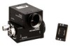
XC-ST70/70CE LOCATION OF PARTS AND OPERATION XC-ST70/70CE 2 CCD VIDEO CAMERA MODULE 1 XC-ST70 4 5 1 Lens mount section A commercial C-mount lens as well as a Sony standard lens can be used. 2 Camera mounting reference hole These screw holes are positionned with high precision related to CCD sensor. 3 Screw hole for tripod adaptor mounting (VCT-ST70I) 2 3 67 3 4 4 12-pin multi-connector DC IN/SYNC (DC power/sync signal input) 5 BNC connector VIDEO OUT 6 Gamma correction ON/OFF selector switch 5 8 A B= 9 412-pin multi-connector Pin No. External HD/VD synchronization Internal HD/VD synchronization External VS synchronization 1 GND GND GND 2 +12 V +12 V +12 V 3 GND GND GND 4 VIDEO output VIDEO output VIDEO output 5 GND GND GND 6 External HD input Internal HD output - 7 *1 External VD input Internal VD output VS 8 GND GND GND 9 - - - 10 *2 WEN output *2 WEN output *2 WEN output 11 TRIG input TRIG input TRIG input 12 GND GND GND *1: An input VD signal is required when the restart/reset mode is used. *2: A WEN output signal is valid only in the external trigger shutter mode. • Factory-setting mode of rear panel Corresponding No. Switch Factory-setting mode 6 Gamma correction ON/OFF selector switch OFF 7 Internal/external sync selector switch EXT 8 Trigger polarity selector switch + 9 75-ohm termination selector switch ON Selection DIP switch A 1, 2, 3, 4: Selects the Shutter speed. OFF 5: Selects the field and frame. (All set to 6, 7, 8: Selects the normal shutter, external trigger shutter, and restart/reset. the left.) B GAIN switch FIX 7 Internal/external sync selector switch The camera operates with internal synchronization when there is no external sync input signal in the EXT position. In this case, an HD/VD signal is not output from the 12-pin multi-connector. 8 Trigger polarity selector switch This switch can select the polarity (negative or positive) of a trigger pulse. 9 75 Ω termination selector switch 0 Selection DIP switch Switches 1 to 4: Selects the shutter speed. Switch 5: Selects the frame or field integration. Switches 6 to 8: Selects the normal shutter, external trigger shutter, and restart/reset. A GAIN switch A: Outputs a fixed-level video signal according to the brightness of a subject. (Variable range: 0 to 18 dB) F: Fixed gain 0 dB M: Variable gain (Manual) M (during factory setting): Adjusted so that all XC-ST70/70CEs are the same in sensitivity (set by Sony's standard value) according to the deviation in sensitivity of CCD. Valid when multiple XC-ST70/70CEs are used for an identical subject. B Volume control switch This switch can be changed in the range of 0 to 18 dB when the GAIN switch is set to "M". During factory setting, this switch is adjusted to the fixed sensitivity for a standard subject. 5
-
 1
1 -
 2
2 -
 3
3 -
 4
4 -
 5
5 -
 6
6 -
 7
7 -
 8
8 -
 9
9 -
 10
10 -
 11
11 -
 12
12 -
13
-
14
-
15
-
16
-
17
-
18
-
19
-
20
-
21
-
22
-
23
-
24
-
25
-
26
-
27
-
28
-
29
-
30
-
31
 |
 |
