Sub-Zero 642 Built-In Installation Guide - Page 11
Water Line, Level, Built-in - service ice
 |
View all Sub-Zero 642 manuals
Add to My Manuals
Save this manual to your list of manuals |
Page 11 highlights
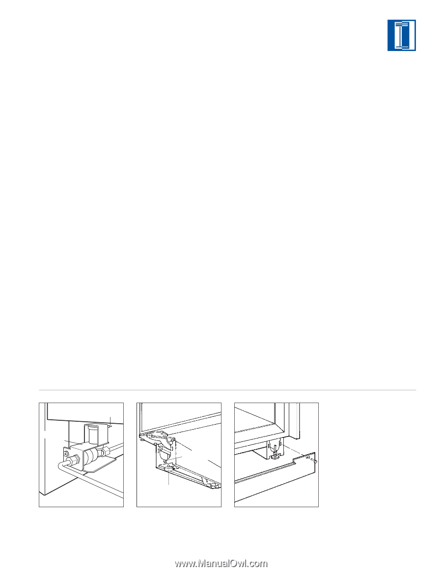
B U I LT- I N I N S TA L L A T I O N I N S T R U C T I O N S WAT E R L I N E C O N N E C T I O N LEVEL THE UNIT To connect the ice maker water line, remove the 1/4" compression fitting from its plastic bag and join the water supply line to the solenoid valve. Refer to illustration 7 below. NOTE: The water valve can be removed from the mounting bracket to gain easier access to water connection. Be sure to purge the line before making the final connection. IMPORTANT NOTE: Turn on the water supply and check all fittings for leaks. Make certain the electrical harness is attached to the solenoid. In areas with water of high mineral content, the use of an in-line water filter is recommended. Make sure the filter is positioned and accessible for replacement when necessary. IMPORTANT NOTE: Let your customer know that the ice maker will not fill with water immediately, and that the first few batches of ice produced should be discarded. Allow 24 hours for proper ice production. Once the unit is in position, extend the front leveling legs down by turning the legs counterclockwise and adjust the height. The rear height adjustment can be made from the front of the base. Turn the 5/16" hex bolt clockwise to raise the unit or counterclockwise to lower it. Refer to illustration 8 below. When the unit is leveled properly, or squared off, door adjustments are less likely to be necessary. IMPORTANT NOTE: Be sure to reference leveling of the unit to the floor and not to surrounding cabinetry. This could affect the operation of the unit, such as door(s) not closing properly. For proper alignment, place the level on the top and side of the unit's main frame for leveling reference points. After the unit has been leveled, make sure the drain pan is installed properly and install the kickplate. Refer to illustration 9 below. IMPORTANT NOTE: The kickplate must be removed for servicing. The floor cannot interfere with removal. Refer to label mounted on kickplate support for height clearance. Replace the grille by reversing the procedure outlined on page 9. If you're using a panel grille, see Overlay Grille Panels on page 17. Turn power back on to the wall outlet. SOLENOID VALVE ELECTRICAL CONNECTION REAR ADJUSTMENT FRONT LEVELERS Illus. 7 Illus. 8 Illus. 9 Dimensions in parentheses are in millimeters unless otherwise specified. 11
-
 1
1 -
2
-
3
-
4
-
5
-
 6
6 -
 7
7 -
 8
8 -
 9
9 -
 10
10 -
 11
11 -
 12
12 -
 13
13 -
 14
14 -
 15
15 -
 16
16 -
17
-
18
-
19
-
20
-
21
-
22
-
23
-
24
 |
 |