TEAC R2 Service Manual - Page 4
Adjustments And Checks
 |
View all TEAC R2 manuals
Add to My Manuals
Save this manual to your list of manuals |
Page 4 highlights
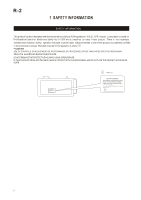
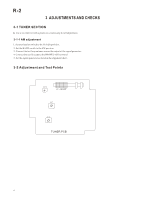
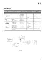
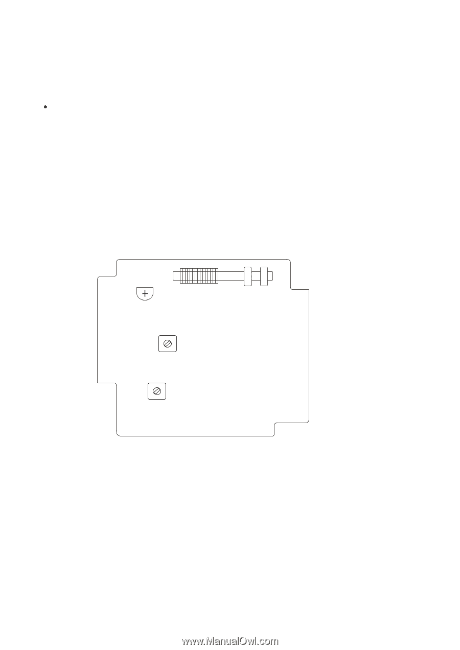
R-2 3 ADJUSTMENTS AND CHECKS 3-1 TUNER SECTION Use a screwdriver with a plastic or ceramic grip for all adjustment. 3-1-1 AM adjustment 1. Set the function switch to the TUNER position. 2. Set the BAND switch to the AM position. 3. Connect the test loop antenna across the output of the signal generator. 4. Connect the oscilloscope to the PHONE JACK terminal. 5. Set the signal generator as listed in the alignment chart. 3-2 Adjustment and Test Points TC1 L3 AM ANT L2 L1 TUNER PCB 4
-
 1
1 -
 2
2 -
 3
3 -
 4
4 -
 5
5 -
 6
6 -
 7
7 -
 8
8 -
 9
9 -
 10
10 -
11
-
12
-
13
-
14
-
15
-
16
-
17
-
18
-
19
-
20
-
21
 |
 |
3 ADJUSTMENTS AND CHECKS
Use a screwdriver with a plastic or ceramic grip for all adjustment.
3-1 TUNER SECTION
1. Set the function switch to the TUNER position.
3. Connect the test loop antenna across the output of the signal generator.
4. Connect the oscilloscope to the PHONE JACK terminal.
5. Set the signal generator as listed in the alignment chart.
3-1-1 AM adjustment
3-2 Adjustment and Test Points
4
R-2
TUNER PCB
L2
L3 AM ANT
L1
TC1
2. Set the BAND switch to the AM position.