TP-Link EAP225 EAP225EU V1 Quick Install Guide - Page 1

TP-Link EAP225 Manual

Page 1 highlights

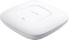
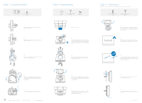
TP-LINK® The Reliable Choice Quick Installation Guide AC1200 Wireless Dual Band Gigabit Access Point EAP225 7106506609 REV1.0.1 Ei Hardware Overview LED Indication Solid green The device is working properly. Flashing yellow Firmware update is in progress. Do not disconnect or power off the device. Flashing red System errors. RAM, Flash, Ethernet, WLAN or firmware may be malfunctioning. MEM Double-flashing red, green, yellow The device is being reset to its factory default settings. 4 Power Supply EAP can be powered via a PSE device (such as a PoE switch) or a power adapter. Via PoE Switch TP-LINK nnnnnnnn 00u00000 PoE Switch Connect the Ethernet cable from the PoE switch to the ETHERNET port. 0 Network Topology Requirement Internet (=, fkl EAP Controller Controller Host TP-LINK Router TP-LI K nnnnn 00000 Switch • A DHCP server (typically a router) is required to assign IP addresses to the EAP and clients in your local network. • A computer running the EAP Controller software, which can be in the same or different subnet with the EAPs. Interface Panel Kv RESOET 7 TA PZO RESET With the device powered on, press and hold the button for about 8 seconds until the LED flashes red, then release the button. The device will restore to factory default settings. ETHERNET The port is used to connect to a router or a switch to transmit data or to a PSE (Power Sourcing Equipment), such as a PoE switch, for both data transmission and Power over Ethernet (PoE) through Ethernet cabling. POWER This port is used to connect to the provided power adapter to power the EAP. The other end of the power adapter connects to a standard electrical wall outlet. Via Power Adapter r P-LEMC nnnnnnnn 00 00000 Switch Plug one end of the provided power adapter into the POWER port of the EAP and the other end to a standard electrical wall outlet. (Th (Th 0 7 10 Hardware Installation The EAP can be ceiling rail mounted, ceiling-mounted, and wall-mounted. The instructions for various mounting options are on the back of this Quick Installation Guide. Option 1: Ceiling Rail Mounting

  • 1
  • 2

TP-LINK®
The
Reliable
Choice
0
Network
Topology
Requirement
Quick
Installation
Guide
AC1200
Wireless
Dual
Band
Gigabit
Access
Point
EAP225
7106506609
REV1.0.1
Ei
Hardware
Overview
4
LED
Indication
Solid
green
The
device
is
working
properly.
Flashing
red
System
errors.
RAM,
Flash,
Ethernet,
WLAN
or
firmware
may
be
malfunctioning.
Power
Supply
fkl
EAP
Controller
Controller
Host
Internet
Router
Switch
A
DHCP
server
(typically
a
router)
is
required
to
assign
IP
addresses
to
the
EAP
and
clients
in
your
local
network.
A
computer
running
the
EAP
Controller
software,
which
can
be
in
the
same
or
different
subnet
with
the
EAPs.
Flashing
yellow
Firmware
update
is
in
progress.
Do
not
disconnect
or
power
off
the
device.
MEM
Double
-flashing
red,
green,
yellow
The
device
is
being
reset
to
its
factory
default
settings.
Interface
Panel
K
v
RESOET
7
T
A
PO
Z
RESET
With
the
device
powered
on,
press
and
hold
the
button
for
about
8
seconds
until
the
LED
flashes
red,
then
release
the
button.
The
device
will
restore
to
factory
default
settings.
ETHERNET
The
port
is
used
to
connect
to
a
router
or
a
switch
to
transmit
data
or
to
a
PSE
(Power
Sourcing
Equipment),
such
as
a
PoE
switch,
for
both
data
transmission
and
Power
over
Ethernet
(PoE)
through
Ethernet
cabling.
POWER
This
port
is
used
to
connect
to
the
provided
power
adapter
to
power
the
EAP.
The
other
end
of
the
power
adapter
connects
to
a
standard
electrical
wall
outlet.
EAP
can
be
powered
via
a
PSE
device
(such
as
a
PoE
switch)
or
a
power
adapter.
Via
PoE
Switch
PoE
Switch
Connect
the
Ethernet
cable
from
the
PoE
switch
to
the
ETHERNET
port.
Via
Power
Adapter
r
Switch
Plug
one
end
of
the
provided
power
adapter
into
the
POWER
port
of
the
EAP
and
the
other
end
to
a
standard
electrical
wall
outlet.
(=,
(Th
(Th
0
10
Hardware
Installation
7
The
EAP
can
be
ceiling
rail
mounted,
ceiling
-mounted,
and
wall
-mounted.
The
instructions
for
various
mounting
options
are
on
the
back
of
this
Quick
Installation
Guide.
Option
1:
Ceiling
Rail
Mounting
Option
2:
Ceiling
Mounting
Option
3:
Wall
Mounting
<f)
O
El
Software
Configuration
To
quickly
set
up
a
wireless
network
connection
with
mass
EAPs,
please
follow
the
steps
below.
Note:
The
IP
address
of
the
management
computer
must
be
reachable
for
the
EAPs
in
the
network.
Step
1:
Installing
the
EAP
Controller
Find
the
EAP
Controller
application
file
from
our
website
at
www.tp-link.com
Run
the
file
and
follow
the
wizard
to
install
the
EAP
Controller
on
the
computer.
Step
2:
Configuring
the
EAP
Controller
Launch
the
EAP
Controller
and
follow
the
configuration
wizard
to
create
a
primary
wireless
network.
After
the
wizard
is
finished,
a
login
screen
will
appear.
Enter
the
admin
name
and
password
you
created
and
click
Sign
In
Step
3:
Adopting
the
EAP
devices
Adopt
the
EAP
devices
in
the
Controller
management
interface
to
change
the
status
from
pending
to
connected
For
More
Configurations
Now
you
can
manage
your
wireless
network
and
view
network
statistic
using
the
EAP
Controller.
Please
refer
to
the
EAP
Controller
User
Guide
to
learn
more
information
on
configuring
and
using
the
Controller
software.