TP-Link T1500-28PCT TL-SL2428P T1500-28PCT V1 Quick Install Guide - Page 9
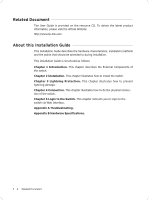
Port Feature, Reset, 100Mbps RJ45 Port, 100/1000Mbps RJ45 Port, SFP Port
 |
View all TP-Link T1500-28PCT TL-SL2428P manuals
Add to My Manuals
Save this manual to your list of manuals |
Page 9 highlights
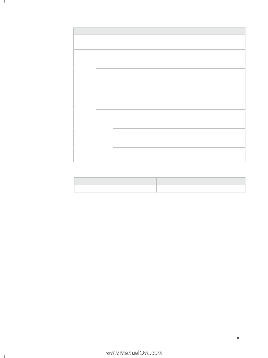
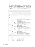
Smart PoE Switch LED FAN PoE Max 10/100M or PoE 1000M Status Green Yellow On Flashing Off Green On Flashing Yellow Off On Flashing On Green Flashing Yellow Off On Flashing Indication All the fans work properly Not all the fans work properly The remaining PoE power≤7W The remaining PoE power keeps ≤7W after this LED is on for 2 minutes The remaining PoE power>7W The port is supplying power normally The supply power exceeds the correponding port's maximum power Overload or short circuit is detected Power-on self-test has failed No PoE power supply is provided on the port A 1000Mbps device is connected to the corresponding port, but no activity Data is being transmitted or received A 10/100Mbps device is connected to the corresponding port, but no activity Data is being transmitted or received No device is connected to the corresponding port Port Feature Model 10/100Mbps RJ45 Port 10/100/1000Mbps RJ45 Port T1500-28PCT 24 4 SFP Port 2 Reset With the switch powered on, press Reset button for 5 seconds to reset the software setting to its factory default settings. 10/100Mbps RJ45 Port Designed to connect to the device with a bandwidth of 10Mbps or 100Mbps. Each has a corresponding 10/100M or PoE LED. 10/100/1000Mbps RJ45 Port Designed to connect to the device with a bandwidth of 10Mbps, 100Mbps or 1000Mbps. Each has a corresponding 1000M LED. SFP Port Designed to install the SFP module. T1500-28PCT features some SFP transceiver slots that are shared with the associated RJ45 ports. The associated two ports are referred as a "Combo" port, which means they cannot be used simultaneously, otherwise only SFP port works. Meanwhile, the associated two ports share the same LED. For T1500-28PCT, Port 27 shares the same LED with Port 27F and Port 28 shares the same LED with Port 28F. Introduction 03
-
 1
1 -
2
-
3
-
 4
4 -
 5
5 -
 6
6 -
 7
7 -
 8
8 -
 9
9 -
 10
10 -
 11
11 -
 12
12 -
 13
13 -
 14
14 -
15
-
16
-
17
-
18
-
19
-
20
-
21
-
22
-
23
-
24
-
25
-
26
-
27
-
28
 |
 |