TP-Link TL-ER5120 TL-ER5120 Installation Guide - Page 18
Verify Installation, ´1´, Power
 |
View all TP-Link TL-ER5120 manuals
Add to My Manuals
Save this manual to your list of manuals |
Page 18 highlights
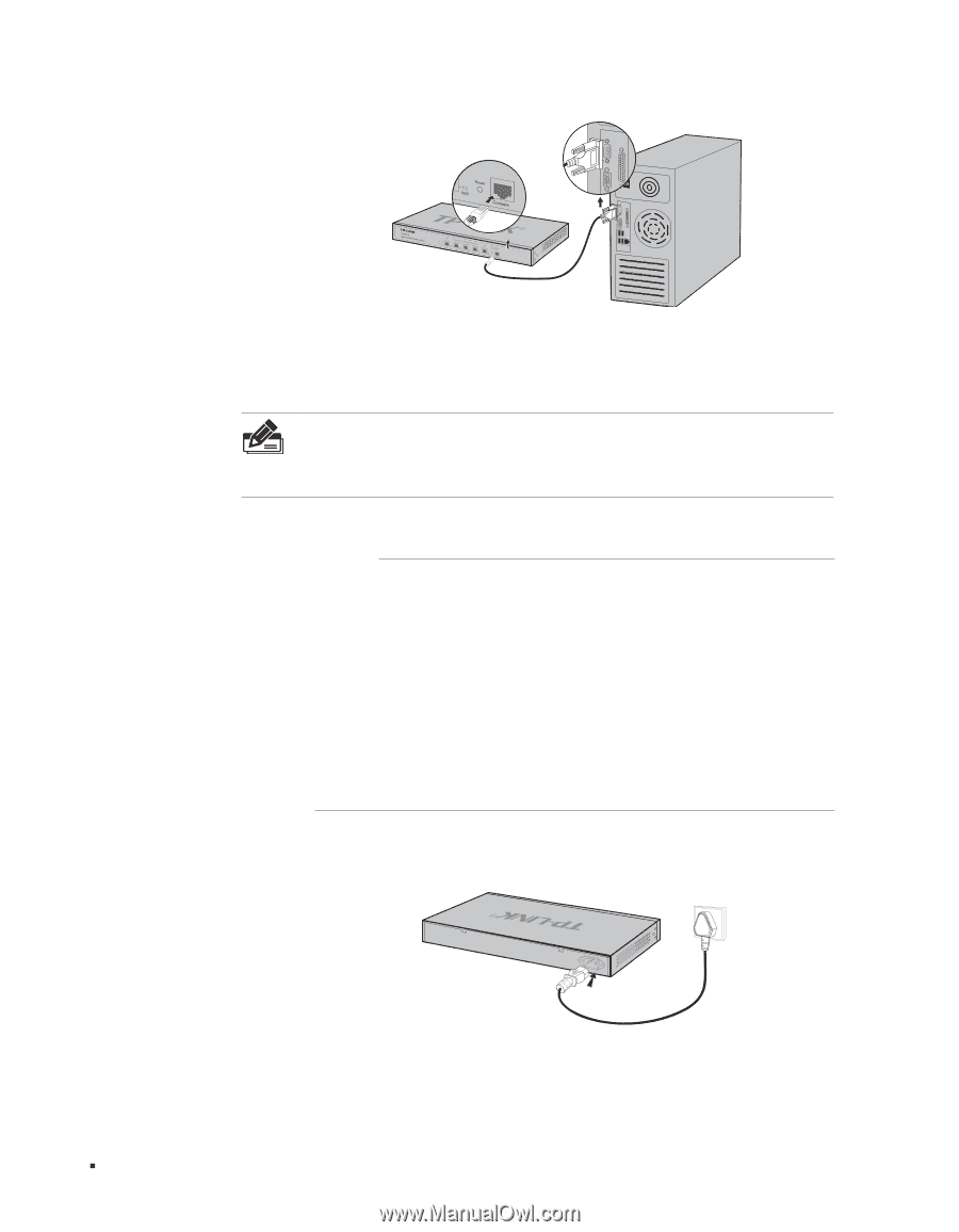
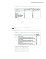
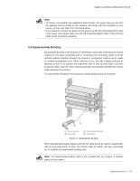
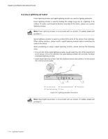
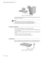
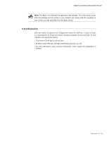
Gigabit Load Balance Broadband Router FFFFFFFFFFFFConnecting the Console Port You can also manage the device through the console port, for details please refer to the User Guide on the resource CD. Note: ■■ The console port is the first port on the right of the front panel. ■■ Please keep the device power off when you plugging the console cable. ■■ Do not connect the console port with other ports by RJ45 cable. 4444Verify Installation After completing the installation, please verify the following items: ■■ There are 5~10cm of clearance around the sides of the device for ventilation and the air flow is adequate. ■■ The voltage of the power supply meets the requirement of the input voltage of the device. ■■ The power socket, device and rack are well grounded. ■■ The device is correctly connected to other network devices. 4444Power On Plug in the negative connector of the provided power cord into the power socket of the device, and the positive connector into a power outlet as the following figure shown. 13 Connection FFFFFFFFFFFFConnecting to Power Supply
-
 1
1 -
2
-
3
-
4
-
5
-
6
-
7
-
8
-
9
-
10
-
11
-
12
-
 13
13 -
 14
14 -
 15
15 -
 16
16 -
 17
17 -
 18
18 -
 19
19 -
 20
20 -
 21
21 -
 22
22 -
 23
23 -
24
-
25
-
26
-
27
-
28
 |
 |