TP-Link TL-SF1016 User Guide - Page 5
Identifying External Components - 16 port ethernet switch
 |
UPC - 845973020040
View all TP-Link TL-SF1016 manuals
Add to My Manuals
Save this manual to your list of manuals |
Page 5 highlights
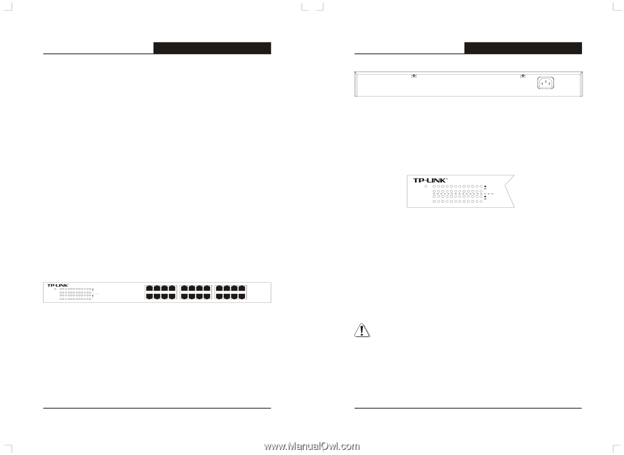
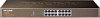
TL-SF1016/TL-SF1024/TL-SF1048 10/100M Fast Ethernet Switch User's Guide 2.3 Power on The TL-SF1016/TL-SF1024/TL-SF1048 16/24/48-port 10/100M Switch is powered by an AC Power Supply. Connect the Switch and power outlet by power cord. Powering on the Switch, it will be automatically initialized and the LED indicators should respond as follows: 1) All of the LED indicators will flash momentarily for one second, which represent a resetting of the system. 2) The Power LED indicator will light up. Chapter 3: Identifying External Components This Chapter describes the front panel, rear panel and LED indicators of the Switch. 3.1 Front Panel The front panel of TL-SF1024 consists of switch model, switch LED indicators, and 24 10/100Mbps RJ-45 ports. TL-SF1024 Power 1 3 5 7 9 11 13 15 17 19 21 23 2 4 6 8 10 12 14 16 18 20 22 24 10/100Mbps Fast Ethernet Switch Link Act 100Mbps Link Act 100Mbps 1 3 5 7 9 11 13 15 17 19 21 23 2 4 6 8 10 12 14 16 18 20 22 24 Figure 3-1 TL-SF1024 Switch Front Panel sketch 3.2 Rear Panel The rear panel of TL-SF1024 only features an electrical outlet, which is an AC electrical outlet. Connect the female of the power cord head here, and the male head to the AC power. 4 TL-SF1016/TL-SF1024/TL-SF1048 10/100M Fast Ethernet Switch User's Guide 100-240V~ 50-60Hz 0.6A Figure 3-2 TL-SF1024 Switch Rear Panel sketch 3.3 LED indicators The LED indicators include Power, Link/Act LED indicators, which are used for monitoring and pre-troubleshooting of the Switch. The following section shows the LED indicators of the Switch along with an explanation of each indicator. TL-SF1024 Power 1 3 5 7 9 11 13 15 17 19 21 23 2 4 6 8 10 12 14 16 18 20 22 24 10/100Mbps Fast Ethernet Switch Link Act 100Mbps Link Act 100Mbps Figure 3-3 TL-SF1024 Switch LEDs sketch Ø Power LED: This indicator will light solid red when the Switch powers up. If the LED is not lit, please check the power supply and connection. Ø LINK/ACT LED: The LED indicates Link/Active status. The corresponding LED indicator will light solid green when connected to a network device. It flashes green when data is being transmitted or received on the working connection. Ø 100Mbps: The corresponding gigabit port LED indicator will light solid green when it's working on 100Mbps speed, not lit when working on 10Mbps speed. Note: Because of the difference of among the mode of switch,Some switch don't include the 100Mbps indicator,such as TL-SF1048 and a few of TL-SF1016 switch. 5
-
 1
1 -
 2
2 -
 3
3 -
 4
4 -
 5
5 -
 6
6
 |
 |