TP-Link TL-SG1005D User Guide - Page 8
Identifying External Components - green
 |
UPC - 696726100515
View all TP-Link TL-SG1005D manuals
Add to My Manuals
Save this manual to your list of manuals |
Page 8 highlights
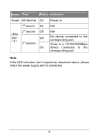
Chapter 2 Identifying External Components This Chapter describes the front panel and rear panel of the Switch. 2.1 Front Panel Figure 2-1 TL-SG1008D Switch Front Panel The Switch's LEDs are located on the front panel: ¾ Power LED: This indicator will light up when the Switch powers up. ¾ LEDs (1~8): The LED indicates Link/Active status. The corresponding LED indicator will light solid green when connected to a network device. It flashes green when data is being transmitted or received on the working connection. Note: The LEDs' description above explains the device's working status after initialization. 2.2 Rear Panel Figure 2-2 TL-SG1008D Switch Rear Panel 4
-
 1
1 -
2
-
 3
3 -
 4
4 -
 5
5 -
 6
6 -
 7
7 -
 8
8 -
 9
9 -
 10
10 -
 11
11 -
 12
12
 |
 |

4
Chapter 2 Identifying External Components
This Chapter describes the front panel and rear panel of the
Switch.
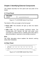
2.1 Front Panel
Figure 2-1 TL-SG1008D Switch Front Panel
The Switch’s LEDs are located on the front panel:
¾
Power LED:
This indicator will light up when the Switch
powers up.
¾
LEDs (1~8):
The LED indicates Link/Active status. The
corresponding LED indicator will light solid green when
connected to a network device. It flashes green when data is
being transmitted or received on the working connection.
Note:
The LEDs’ description above explains the device’s working
status after initialization.
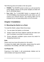
2.2 Rear Panel
Figure 2-2 TL-SG1008D Switch Rear Panel