TP-Link TL-SG1024D User Guide - Page 7
Identifying External Components - model
 |
UPC - 845973020620
View all TP-Link TL-SG1024D manuals
Add to My Manuals
Save this manual to your list of manuals |
Page 7 highlights
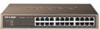
Chapter 2 Identifying External Components This Chapter describes the front panel, rear panel and LED indicators of the Switch. TL-SG1008/TL-SG1016D/TL-SG1024D just differ in the number of LED indicators and ports and all figures in this guide are of TL-SG1008. 2.1 Front Panel The front panel of TL-SG1008 consists of switch model, switch LED indicators, and 8 10/100/1000Mbps RJ-45 ports. Figure 2-1 TL-SG1008 Switch Front Panel sketch The LED indicators include Power, Link/Act LED indicators, which are used for monitoring and pre-troubleshooting of the Switch. The following section shows the LED indicators of the Switch along with an explanation of each indicator. ¾ POWER LED: This indicator will light solid red when the Switch powers up. If the LED is not lit, please check the power supply and connection. ¾ Link/Act LED: The LED indicates Link/Active status. The corresponding LED indicator will light solid green when connected to a network device. It flashes green when data is being transmitted or received on the working connection. ¾ 1000Mbps LED: The corresponding port LED indicator will light solid green when it's working on 1000Mbps speed. Not lit indicates working on 10/100Mbps speed. 2.2 Rear Panel The rear panel of TL-SG1008 features a power socket and a Grounding Terminal (marked with ). Figure 2-2 TL-SG1008 Switch Rear Panel sketch ¾ Grounding Terminal: TL-SG1008 already comes with Lightning Protection Mechanism. You can also ground the Switch through the PE (Protecting Earth) 3
-
 1
1 -
 2
2 -
 3
3 -
 4
4 -
 5
5 -
 6
6 -
 7
7 -
 8
8 -
 9
9 -
 10
10 -
 11
11 -
 12
12 -
13
-
14
-
15
-
16
 |
 |
