TP-Link TL-SL2210 TL-SL2210 V1 IG 7106504458 - Page 8
Rear Panel
 |
View all TP-Link TL-SL2210 manuals
Add to My Manuals
Save this manual to your list of manuals |
Page 8 highlights
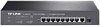
Smart Switch Port Feature Model TL-SL2210 TL-SL2218 TL-SL2428 TL-SL2452 10/100Mbps RJ45 Port 8 16 24 48 10/100/1000Mbps RJ45 Port 1 2 4 2 SFP Port 1 2(Combo1 2(Combo1 2 Reset(RESET) With the switch powered on, press Reset button for five seconds to reset the software setting to its factory default settings. 10/100Mbps RJ45 Port Designed to connect to the device with a bandwidth of 10Mbps or 100Mbps. Each has a corresponding 10/100M LED. 10/100/1000Mbps RJ45 Port Designed to connect to the device with a bandwidth of 10Mbps, 100Mbps or 1000Mbps. Each has a corresponding 1000M LED. SFP Port Designed to install the SFP module. TL-SL2218/TL-SL2428 features some SFP transceiver slots that are shared with the associated RJ45 ports. The associated two ports are referred as a "Combo" port, which means they cannot be used simultaneously, otherwise only SFP port works. Meanwhile, the associated two ports share the same LED. For TL-SL2218, Port 17 shares the same LED with Port 17F and Port 18 shares the same LED with Port 18F; for TL-SL2428 Port 27 shares the same LED with Port 27F and Port 28 shares the same LED with Port 28F. ■■ Rear Panel The rear panel of TL-SL2210 is shown as Figure 1-5. Grounding Terminal Power Socket FFFFFFFFFFFFRear Panel of TL-SL2210 03 Introduction
-
 1
1 -
2
-
 3
3 -
 4
4 -
 5
5 -
 6
6 -
 7
7 -
 8
8 -
 9
9 -
 10
10 -
 11
11 -
 12
12 -
 13
13 -
14
-
15
-
16
-
17
-
18
-
19
-
20
-
21
-
22
-
23
-
24
-
25
-
26
-
27
-
28
 |
 |
