TRENDnet TV-IP301W User's Guide - Page 13
Rear Panel - reset
 |
UPC - 710931303315
View all TRENDnet TV-IP301W manuals
Add to My Manuals
Save this manual to your list of manuals |
Page 13 highlights
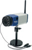
Rear Panel 1. Antenna (TV-IP301W) 2. Mic-In Connector 8. I/O Connector 7. Reset Button 6. Network Cable Connector 5. Iris Level 4. Power/Link LEDs 3. DC Power Connector 1. Detachable Antenna (TV-IP301W) The detachable external antenna allows you to adjust its position to obtain the maximum signal. 2. Mic-In Connector This connector allows you to connect an external microphone. 3. DC Power Connector The DC power input connector is located on the camera's rear panel, and is labeled DC 12V with a single jack socket to supply power to the camera. Power will be generated when the power supply is connected to a wall outlet. 12
-
 1
1 -
2
-
3
-
4
-
5
-
6
-
7
-
 8
8 -
 9
9 -
 10
10 -
 11
11 -
 12
12 -
 13
13 -
 14
14 -
 15
15 -
 16
16 -
 17
17 -
 18
18 -
19
-
20
-
21
-
22
-
23
-
24
-
25
-
26
-
27
-
28
-
29
-
30
-
31
-
32
-
33
-
34
-
35
-
36
-
37
-
38
-
39
-
40
-
41
-
42
-
43
-
44
-
45
-
46
-
47
-
48
-
49
-
50
-
51
-
52
-
53
-
54
-
55
-
56
-
57
-
58
-
59
-
60
-
61
-
62
-
63
-
64
-
65
-
66
-
67
-
68
-
69
-
70
-
71
-
72
-
73
-
74
-
75
-
76
-
77
-
78
-
79
-
80
-
81
-
82
-
83
-
84
-
85
-
86
-
87
-
88
-
89
-
90
-
91
-
92
-
93
-
94
-
95
-
96
-
97
-
98
-
99
-
100
-
101
-
102
-
103
-
104
-
105
-
106
-
107
-
108
-
109
-
110
-
111
-
112
-
113
-
114
-
115
-
116
-
117
-
118
-
119
 |
 |

12
Rear Panel
1. Detachable Antenna
(TV-IP301W)
The detachable external antenna allows you to adjust its position
to obtain the maximum signal.
2. Mic-In Connector
This connector allows you to connect an external microphone.
3. DC Power Connector
The DC power input connector is located on the camera’s rear
panel, and is labeled DC 12V with a single jack socket to supply
power to the camera. Power will be generated when the power
supply is connected to a wall outlet.
1. Antenna
(TV-IP301W)
6. Network Cable
Connector
7. Reset Button
3. DC Power Connector
8. I/O Connector
5. Iris Level
2. Mic-In Connector
4. Power/Link LEDs