Tecumseh Products H30 Operator Manual - Page 9
Engines with Electric Starters - troubleshooting
 |
View all Tecumseh Products H30 manuals
Add to My Manuals
Save this manual to your list of manuals |
Page 9 highlights
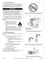
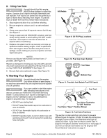
A. Engines with Electric Starters Only one of the following two sections will apply to your engine. See Table 3. Table 3. Engine Sections with Electric Starter If your engine has: Primer Bulb Only Choke Only Go to: Section A.I Section A.II I. Engine With Primer Bulb 1. To avoid carbon monoxide poisoning, ensure engine is outdoors in a well-ventilated area. 2. Be sure fuel valve (optional) is open and all switches are on. See Figure 13. 3. Move Equipment Control (see equipment manufacturer's instructions) or Engine Throttle Control to "FAST" position or "HIGH" position. See Figures 14 and 15. NOTE Some engines are equipped with an optional Spring Loaded Throttle Control. This spring loaded control is used to ensure the throttle will return to engine idle speed if it is released or if the cable fails. The throttle control must be in the idle position when starting engine. 4. When starting a cold engine, push primer bulb firmly with your thumb 3 times, allowing primer bulb to return completely to original position between pushes. See Figure 16. NOTES Cooler temperatures may require pushing primer bulb firmly with your thumb 5 times. DO NOT use primer to restart a warm engine after a short shutdown. Doing so will flood the engine and may result in equipment malfunction. DO NOT operate an electric starter for more than 5 seconds each attempt. 5. Push starter button or turn ignition switch key (see equipment manufacturer's instructions) to start engine. 6. When engine starts, release starter button or ignition switch key. 7. If engine fails to start after 3 attempts, repeat steps 2 thru 6 and try again. 8. If engine does not start after following steps 1 thru 7, contact your Authorized Tecumseh Servicing Dealer. DO NOT attempt to start or troubleshoot this engine in any other way. Fuel Tank Turn Valve Clockwise To "Off" Position Fuel Valve "Open" Position Shown Figure 13. Optional Fuel Valve Positions STOP STOP SLOW RUN FAST CHOKE PRIMER Figure 14. Typical Engine Symbols Remote Models All Other Models 1 2 3 1. High Speed 2. Low Speed 3. Stop Figure 15. Engine Speed Control Levers 181-789-14 Figure 16. Primer Bulb Four-Cycle Engine • Horizontal Crankshaft • Air-Cooled Page 7
-
 1
1 -
2
-
3
-
 4
4 -
 5
5 -
 6
6 -
 7
7 -
 8
8 -
 9
9 -
 10
10 -
 11
11 -
 12
12 -
 13
13 -
 14
14 -
15
-
16
-
17
-
18
-
19
-
20
-
21
-
22
-
23
-
24
 |
 |
