Tecumseh Products OHM110 Operator Manual - Page 12
Engines with Recoil Starters
 |
View all Tecumseh Products OHM110 manuals
Add to My Manuals
Save this manual to your list of manuals |
Page 12 highlights
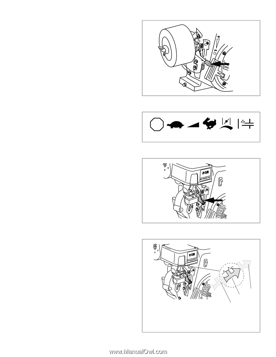
B. Engines with Recoil Starters 1. To avoid carbon monoxide poisoning, be sure engine is outdoors in a well-ventilated area. 2. Be sure fuel valve, if present (see equipment manufacturer's instructions) is open and all switches are on. 3. Move engine speed control to "FAST" position. See Figures 21 thru 23 4. Set choke control to "FULL CHOKE" position (see equipment manufacturer's instructions). See Figures 24 thru 26. Afterward, continue reading instructions below. NOTE If restarting a warm engine after a short shutdown, move engine speed control to "FAST" position and move choke control to "NO CHOKE" position. Figure 21. Engine Mounted Speed Control STOP STOP SLOW RUN FAST CHOKE PRIMER Figure 22. Typical Engine Symbols Climate Guard ! RUN CHOKE Page 10 Figure 23. Engine Components Climate Guard ! RUN CHOKE 1. "NO CHOKE" Position 2. "1/2 CHOKE" Position 3. "FULL CHOKE" Position 3 2 1 Figure 24. Choke Control Option "A" Four-Cycle Engine • Horizontal Crankshaft • Air-Cooled 181-719-14
-
 1
1 -
2
-
3
-
4
-
5
-
6
-
 7
7 -
 8
8 -
 9
9 -
 10
10 -
 11
11 -
 12
12 -
 13
13 -
 14
14 -
 15
15 -
 16
16 -
 17
17 -
18
-
19
-
20
-
21
-
22
-
23
-
24
 |
 |