Thermador HPWB48FS Installation Instructions - Page 9
Mount, Installation, Cabinet, Installation
 |
View all Thermador HPWB48FS manuals
Add to My Manuals
Save this manual to your list of manuals |
Page 9 highlights
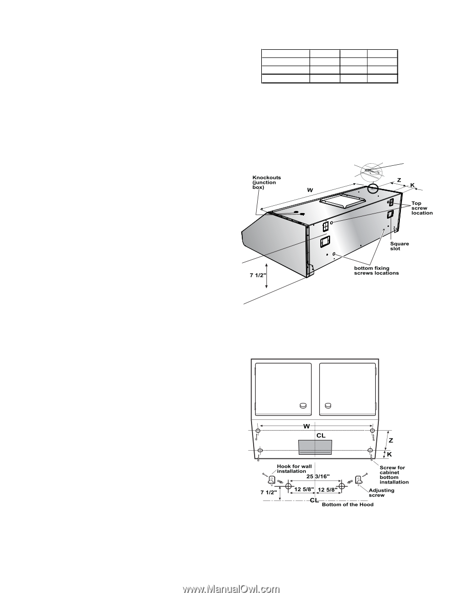
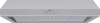
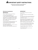
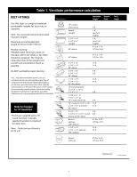
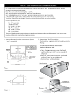
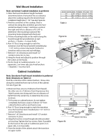
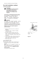
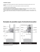
Wall Mount Installation Note: see below if cabinet installation is preferred 3. After the hood installation height has been determined draw a horizontal line at a distance above the cooktop equal to the desired hood installation height plus 7- 1/2". See also Figure 4a. 4. Find the centerline of the cooktop. Draw a vertical line along this centerline up to the horizontal line drawn in step 1 and draw a vertical line right and left at a distance of12-5/8" to determine the mounting locationof the mounting hooks shipped with the hood. 5. Fit two mounting hooks on the wall to hang the hood through the provided slots (2 wall anchors + 2 hooks + 2 screws 5x35). 6. Run 10" Duct, long enough to reach the transition once the hood has been installed plus 1 1/2" inch to connect ductwork. Fix Duct to transition with screws and seal withtape. 7. Remove 1 of 2 knockouts and install 1/2" conduit connector in j-box. 8. Hang the hood and adjust its position through the screws on the hooks. 9. Fix the hood to 4 additional point, 2 on upperside, 2 on lower side (use 4 wall anchors + 4washers + 4 screws 5x35. Cabinet Installation: Note: See above if wall mount installation is preferred Note: Distances on Table. 3.3 Find the centerline of the cabinet bottom. Draw a line along this centerline from rear to front of the cabinet. See also Figure 4b. 4. Draw two lines, one at a K distance from thewall, the other one at a Z distance from theprevious line. Mark 4 points, two along each line at a distance of half W from the center line, to determine the screw locations. 5. Fit 4 screws on cabinet bottom do not tighten completely but leave a space of about 1/2" from cabinet bottom surface and head screws. 6. Run 10" Duct, long enough to reach the transition once the hood has been installed plus1 1/2" inch for connect ductwork. 7. Remove 1 of 2 knockouts and install 1/2"conduit connector in j-box. 8. Hang the hood on screws through side slots provided on hood top.Tighten the four screws. Note: If possible fix the hood on the wall at 4 additional point (2 on upper side, 2 on lowerside). 9. From the inside of the cabinet attach the transition on upper outlet. 9 HOOD W IDTH 30" 36" 48" DIM. "W " DIM. "K " 29 - 1/8" 2 - 1/2" 35 - 1/16" 2 - 1/2" 47 - 1/16" 2 - 1/2" DIM. "Z" 7 - 1/16" 7 - 1/16" 7 - 1/16" Table 3 Figure 4a Side slot x 4 Center Hole Figure 4b
-
 1
1 -
2
-
3
-
 4
4 -
 5
5 -
 6
6 -
 7
7 -
 8
8 -
 9
9 -
 10
10 -
 11
11 -
 12
12 -
 13
13 -
 14
14 -
15
-
16
-
17
-
18
-
19
-
20
-
21
-
22
-
23
-
24
-
25
-
26
 |
 |