Thermador MEDMCW31JP Installation Instructions
Thermador MEDMCW31JP Manual
 |
View all Thermador MEDMCW31JP manuals
Add to My Manuals
Save this manual to your list of manuals |
Thermador MEDMCW31JP manual content summary:
- Thermador MEDMCW31JP | Installation Instructions - Page 1
MASTERPIECE®/THERMADOR PROFESSIONAL® SERIES BUILT-IN OVEN - Thermador MEDMCW31JP | Installation Instructions - Page 2
- Thermador MEDMCW31JP | Installation Instructions - Page 3
Contents 4 Table de Matières 19 Contenido 35 Models/Modèle/Modelo ME301JP ME301JS ME302JP ME302JS MED271JS MED272JS MED301JS MED301JP MED302JS MED302JP MEDMC301JS MEDMC301JP MEDMCW71JS MEDMCW31JP MEDMCW31JS POD301J PODC302J PODM301J PODMW301J - Thermador MEDMCW31JP | Installation Instructions - Page 4
INSTRUCTIONS Service 13 Data Plate 13 Appliance and Cabinet Cutout Dimensions 13 Dimensions for 27" Wall-Mounted Units 13 Dimensions for 27" Under-Counter Units 15 Dimensions for 30" Wall-Mounted Units 15 Dimensions for 30" Under-Counter Units 17 THERMADOR® Support 18 Service 18 Parts - Thermador MEDMCW31JP | Installation Instructions - Page 5
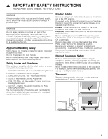
Do not repair, replace or remove any part of the appliance unless specifically recommended in the manuals. Improper installation, service or maintenance can cause injury or property damage. Refer to this manual for guidance. All other servicing should be done by a qualified technician. Appliance - Thermador MEDMCW31JP | Installation Instructions - Page 6
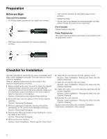
and long sleeves are recommended (to help protect hands and arms from scratches). Parts Included Phillips head screws (6). Power Requirements The outlet must be properly grounded in into the Cabinet Opening" Always read and follow the complete installation instructions contained in this manual. 6 - Thermador MEDMCW31JP | Installation Instructions - Page 7
"Cabinet Dimension Requirements" section at the back of this installation manual for the details pertaining to your particular model. All models above the unit to facilitate connecting and servicing the unit. ▯ The cabinet base must be flat and capable of supporting the weight of your oven when in - Thermador MEDMCW31JP | Installation Instructions - Page 8
supply. Model ME301JP, ME301JS, MED271JS, MED301JS, MED301JP, POD301J ME302JP, ME302JS, MED272JS, MED302JS, MED302JP, PODC302J MEDMC301JS, MEDMC301JP, MEDMCW71JS, MEDMCW31JP, MEDMCW31JS, PODM301J, PODMW301J Circuit Required 30 AMP 40 AMP 50 AMP The electrical supply should be a 4-wire single - Thermador MEDMCW31JP | Installation Instructions - Page 9
cabinet to attach to junction box. To maintain serviceability, the flex conduit must not be shortened and instructions are followed carefully. Please take time to read and follow the instructions shock or burns. ▯ The oven door is heavy and parts of it are fragile. Use both hands to remove the - Thermador MEDMCW31JP | Installation Instructions - Page 10
To remove the oven door: 1. Read the preceeding caution notice before beginning the oven door removal process. 2. Provide a nearby place to safely lay the door after removal so it will not fall over or be stepped upon. Lay the door flat on a blanket or cushioned surface. 3. Open the oven door fully - Thermador MEDMCW31JP | Installation Instructions - Page 11
placing the unit directly into the cabinet opening. Do not allow the metal base of the unit to contact the flooring. See the following handling instructions for details. ▯ To avoid damage to the door (and/or warming drawer front for combo units) do not lift, pull or push the unit during - Thermador MEDMCW31JP | Installation Instructions - Page 12
and the cabinet back wall. If necessary, guide the flexible conduit into the wall or cabinet the BAKE mode. See the Use and Care Manual for detailed operation instructions. 4. Verify that the oven light comes on and service for assistance. Otherwise, the installation is complete at this time. 12 - Thermador MEDMCW31JP | Installation Instructions - Page 13
Manual for troubleshooting information. Refer to the Warranty in the Use and Care Manual. To reach a service representative, see the contact information at the front of the manual oven support, install 2x4's extending front to back flush with the bottom and the side of the opening. The supporting - Thermador MEDMCW31JP | Installation Instructions - Page 14
secured to the floor/ cabinet and level. NOTICES ▯ The conduit box must be located above the unit to facilitate connecting and servicing. ▯ The cabinet base must be flat and capable of supporting a weight of at least 361 lbs (164 kg). It is good practice, when oven is installed at the end of - Thermador MEDMCW31JP | Installation Instructions - Page 15
must be well secured to the floor/ cabinet and level. Note: The cabinet base must be flat and capable of supporting a weight of at least 193 lbs (87 kg). Wall Installation 30" Single Oven: It is good practice, when oven is installed at the end of a - Thermador MEDMCW31JP | Installation Instructions - Page 16
below the unit, a 2 inch diameter hole or space is required between the back wall and the right rear of the 2x4 supports. ▯ The cabinet base must be flat and capable of supporting a weight of at least 390 lbs (177 kg). It is good practice, when oven is installed at the end of - Thermador MEDMCW31JP | Installation Instructions - Page 17
bottom and the side of the opening. The supporting base must be well secured to the floor/ cabinet and level. NOTICES ▯ The conduit box must be located above the unit to facilitate connecting and servicing. ▯ The cabinet base must be flat and capable of supporting a weight of at least 429 lbs (195 - Thermador MEDMCW31JP | Installation Instructions - Page 18
have any questions or in the unlikely event that your THERMADOR® appliance needs service. Our service team is ready to assist you. USA 800-735-4328 www.thermador.com/support Canada 800-735-4328 www.thermador.ca Parts and Accessories Parts, filters, descalers, stainless steel cleaners and more can be - Thermador MEDMCW31JP | Installation Instructions - Page 19
de empaquetage gauche des supports 22 Déplacement de empaquetage droite des supports... 22 Installation électrique Test de vérification 28 Dépannage 28 Avant d'appeler le service de dépannage 28 Plaque signalétique 28 Dimensions de l' THERMADOR 34 Dépannage 34 Pièces et accessoires 34 19 - Thermador MEDMCW31JP | Installation Instructions - Page 20
pour pouvoir le retouver facilement plus tard. Important - Conserver ces instructions pour l´usage de l´inspecteur local en électricité. Avant l´installation, couper le courant au panneau de service. Verrouiller le panneau de service pour éviter que le courant ne soit accidentellement rétabli. Pour - Thermador MEDMCW31JP | Installation Instructions - Page 21
aide-mémoire pour vérifier si vous avez complété chaque étape du processus d'installation. Ceci permet d'éviter certaines erreurs courantes. Consulter les instructions détaillées pour chaque étape dans les sections suivant cet aide-mémoire. 1. Avant l'installation, assurez-vous que les dimensions de - Thermador MEDMCW31JP | Installation Instructions - Page 22
connexion électrique doit être située au dessus de l'unité pour faciliter le branchement et l'alimentation. ▯ La base de l'armoire doit être plane et capable de supporter le poids de votre four en usage (le poids varie selon les modèles et peut atteindre 429 lb (195 kg)). Pour connaître le - Thermador MEDMCW31JP | Installation Instructions - Page 23
Modèle ME301JP, ME301JS, MED271JS, MED301JS, MED301JP, POD301J ME302JP, ME302JS, MED272JS, MED302JS, MED302JP, PODC302J MEDMC301JS, MEDMC301JP, MEDMCW71JS, MEDMCW31JP, MEDMCW31JS, PODM301J, PODMW301J Circuit requis 30 AMP 40 AMP 50 AMP L'appareil doit être alimenté en courant alternatif monophas - Thermador MEDMCW31JP | Installation Instructions - Page 24
fermement et correctement, il y a un risque de lésion corporelle ou de dommage au produit. ▯ Pour éviter toute blessure causée par l'enclenchement soudain du support charnière, s'assurer que les deux leviers sont bien enclenchés avant d'enlever la porte. En outre, ne forcez la porte pour l'ouvrir ou - Thermador MEDMCW31JP | Installation Instructions - Page 25
Retrait de la porte du four : 1. Lire la mise en garde précédente avant de commencer à enlever la porte. 2. Réserver un endroit à proximité pour déposer la porte après l'avoir retirée où elle ne tombera pas et où personne ne lui marchera dessus. Déposer la porte à plat sur une couverture ou une - Thermador MEDMCW31JP | Installation Instructions - Page 26
9. Soulever la porte et la tirer vers le haut tel qu'indiqué dans l'illustration suivante. L'encoche de la charnière se dégagera du cadre de la porte du four. Lorsque les deux charnières de la porte du four sont dégagées, soulever la porte pour l'enlever de l'unité. Lorsque vous soulevez l'unité - Thermador MEDMCW31JP | Installation Instructions - Page 27
3. Guidez l'unité dans l'ouverture de façon à ce qu'elle reste droite. Poussez l'unité au fond de l'armoire jusqu'à ce que la bordure du four soit à environ 2 pouces du mur de l'armoire. Attention de ne pas gêner le boyau qui se trouve entre le four et le mur du fond de l'armoire. Si nécessaire, - Thermador MEDMCW31JP | Installation Instructions - Page 28
Sélectionnez le mode cuisson. Référez-vous au manuel d'utilisation et d'entretien pour les instructions détaillées. 4. Assurez-vous que la lumière du four s'allume et que , contactez le service de dépannage. L'installation est maintenant terminée. Dépannage Avant d'appeler le service de dépannage - Thermador MEDMCW31JP | Installation Instructions - Page 29
ou une ouverture de 2 po (5,8 cm) de diamètre est requis entre le mur arrière et la partie arrière droite des montants de support de 2 poucess sur 4. ▯ Le socle du coffret doit être plate et apte à soutenir un poids d´au moins 193 lb (87 kg). Fours doubles de 27 - Thermador MEDMCW31JP | Installation Instructions - Page 30
moins 369 lb (167 kg). Ce four intégré peut être installé au-dessous d´une surface de cuisson Thermador en autant qu´il n´y a pas de contact entre le bas de la surface de cuisson et le haut du four : La base de l'armoire doit être plane et capable de supporter un poids d'au moins 193 lb (87 kg). 30 - Thermador MEDMCW31JP | Installation Instructions - Page 31
espace ou une ouverture de 2 po (5,8 cm) de diamètre est entre le mur arrière et la partie arrière droite des montants de support de 2 poucess sur 4. ▯ Le socle du coffret doit être plate et apte à soutenir un poids d´au moins 212 lb (96 kg). Fours doubles de 30 - Thermador MEDMCW31JP | Installation Instructions - Page 32
diamètre est entre le mur arrière et la partie arrière droite des montants de support de 2 poucess sur 4. ▯ Le socle du coffret doit être plate et apte à soutenir le mur arrière et la partie arrière droite des montants de support de 2 poucess sur 4. ▯ Le socle du coffret doit être plate et apte à soutenir - Thermador MEDMCW31JP | Installation Instructions - Page 33
soutien doit être bien fixé au plancher ou au coffret et être de niveau. Remarque : La base de l'armoire doit être plane et capable de supporter un poids d'au moins 212 lb (96 kg). 33 - Thermador MEDMCW31JP | Installation Instructions - Page 34
à communiquer avec notre service à la clientèle STAR® si vous avez des questions ou dans l'éventualité peu probable où votre appareil THERMADOR® nécessitait de l'entretien. Notre équipe de dépannage se fera un plaisir de vous aider. États-Unis 800-735-4328 www.thermador.com/support Canada 800-735 - Thermador MEDMCW31JP | Installation Instructions - Page 35
46 Dimensiones para unidades montadas a la pared de 30 pulg 47 Unidades instaladas debajo de la superficie de trabajo de 30 49 Soporte técnico de THERMADOR 49 Servicio técnico 49 Piezas y accesorios 49 35 - Thermador MEDMCW31JP | Installation Instructions - Page 36
que puede causar daños materiales o lesiones personales. AVISO No repare ni cambie ninguna parte del electrodoméstico, a menos que se recomiende específicamente en los manuales. La instalación, servicio técnico o mantenimiento incorrectos pueden causar lesiones o daños materiales. Consulte este - Thermador MEDMCW31JP | Installation Instructions - Page 37
(s) del horno. Sección: Instalación del horno, "Colocar el horno en la abertura del gabinete" Siempre lea y siga las instrucciones de instalación completas incluidas en este manual. 37 - Thermador MEDMCW31JP | Installation Instructions - Page 38
lb [195 kg]). Consulte el peso apropiado para su modelo en la sección "Requisitos de dimensiones del gabinete" que se encuentra en la parte posterior de este manual de instalación. Quitar el embalaje Nota: Para evitar que se dañe su piso, mantenga la unidad en su base de embalaje hasta que est - Thermador MEDMCW31JP | Installation Instructions - Page 39
V CA, 60 Hz. Modelo ME301JP, ME301JS, MED271JS, MED301JS, MED301JP, POD301J ME302JP, ME302JS, MED272JS, MED302JS, MED302JP, PODC302J MEDMC301JS, MEDMC301JP, MEDMCW71JS, MEDMCW31JP, MEDMCW31JS, PODM301J, PODMW301J Circuito requerido 30 AMP 40 AMP 50 AMP El suministro eléctrico debe ser de CA monof - Thermador MEDMCW31JP | Installation Instructions - Page 40
Conexión de tres cables 1 Cable de la fuente de alimentación eléctrica 2 Cables negros 3 Conector de conducto incluido en el listado de UL 4 Cable del horno 5 Cable desnudo o verde 6 Cables blancos 7 Cables rojos 8 Caja de empalme ▯ Conecte el cable rojo del horno al cable rojo del - Thermador MEDMCW31JP | Installation Instructions - Page 41
y los tornillos para la reinstalación. 7. Con los fiadores en su lugar según se indica, cierre la puerta del horno con cuidado hasta que la parte delantera de la puerta se encuentre, aproximadamente, a 5 1/2 pulgadas (140 mm) del panel de control. 8. Tome la puerta firmemente usando ambas manos. La - Thermador MEDMCW31JP | Installation Instructions - Page 42
9. Levante la puerta y jálela hacia afuera en un ángulo ascendente, según se muestra en la siguiente ilustración. La muesca en la pata de la bisagra se desenganchará del marco de la puerta del horno. Con las patas de ambas bisagras de la puerta desenganchadas, levante la puerta para separarla de la - Thermador MEDMCW31JP | Installation Instructions - Page 43
puerta firmemente con las dos manos a un ángulo de 30° con respecto a la parte delantera de la unidad. 2. Dirija las bisagras de la puerta dentro de las ranuras del horno de microondas para lograr un ajuste firme contra la parte delantera del gabinete. Determine si es necesario alinear el marco de - Thermador MEDMCW31JP | Installation Instructions - Page 44
remítase a la información de contacto que aparece en el frente del manual. Cuando llame, tenga a la mano la información impresa en la placa número de serie. Al solicitar servicio técnico, consulte la placa de datos del electrodoméstico. La placa de datos se encuentra en la parte inferior del panel - Thermador MEDMCW31JP | Installation Instructions - Page 45
madera de 2 x 4 de adelante hacia atrás, que estén niveladas con la parte inferior y lateral de la abertura. La base de apoyo debe estar bien asegurada un orificio o espacio de 22" de diámetro entre la pared trasera y la parte posterior derecha de los soportes de 2 x 4. ▯ La base del gabinete debe - Thermador MEDMCW31JP | Installation Instructions - Page 46
lb (167 kg). Se puede instalar este horno empotrado debajo de cualiquier parrillade Thermador mientras no haya contacto entre el piso de la parilla y la parte superior del horno, excepto por la parilla de inducción Thermador, donde el espacio libre debe ser al menos 1 pulgada (vea las ilustraciones - Thermador MEDMCW31JP | Installation Instructions - Page 47
un orificio o espacio de 2" de diámetro entre la pared trasera y la parte posterior derecha de los soportes de 2 x 4. ▯ La base del gabinete debe dejar un orificio o espacio de 2" de diámetro entre la pared trasera y la parte posterior derecha de los soportes de 2 x 4. ▯ La base del gabinete debe - Thermador MEDMCW31JP | Installation Instructions - Page 48
madera de 2 x 4 de adelante hacia atrás, que estén niveladas con la parte inferior y lateral de la abertura. La base de apoyo debe estar bien asegurada un orificio o espacio de 2" de diámetro entre la pared trasera y la parte posterior derecha de los soportes de 2 x 4. ▯ La base del gabinete debe - Thermador MEDMCW31JP | Installation Instructions - Page 49
de madera de 2 x 4 de adelante hacia atrás, que estén niveladas con la parte inferior y lateral de la abertura. La base de apoyo debe estar bien asegurada al piso asistirlo. EE. UU. 800-735-4328 www.thermador.com/support Canadá 800-735-4328 www.thermador.ca Piezas y accesorios Puede comprar piezas, - Thermador MEDMCW31JP | Installation Instructions - Page 50
- Thermador MEDMCW31JP | Installation Instructions - Page 51
- Thermador MEDMCW31JP | Installation Instructions - Page 52
and more can be purchased in the THERMADOR® eShop or by phone. USA Service 800-735-4328 www.thermador.com/support Parts & Accessories www.thermador-eshop.com Canada Service 800-735-4328 www.thermador.ca Parts & Accessories Marcone - 800-287-1627 or Reliable Parts - 800-663-6060 Nous comprenons que
-
 1
1 -
 2
2 -
 3
3 -
 4
4 -
 5
5 -
 6
6 -
 7
7 -
8
-
9
-
10
-
11
-
12
-
13
-
14
-
15
-
16
-
17
-
18
-
19
-
20
-
21
-
22
-
23
-
24
-
25
-
26
-
27
-
28
-
29
-
30
-
31
-
32
-
33
-
34
-
35
-
36
-
37
-
38
-
39
-
40
-
41
-
42
-
43
-
44
-
45
-
46
-
47
-
48
-
49
-
50
-
51
-
52
 |
 |

MASTERPIECE
®
/THERMADOR PROFESSIONAL
®
SERIES
BUILT-IN OVEN