Thermador PCG305W Installation Instructions - Page 14
Gas requirements and hookup, High altitude, Gas requirements
 |
View all Thermador PCG305W manuals
Add to My Manuals
Save this manual to your list of manuals |
Page 14 highlights
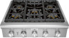
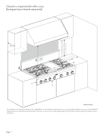
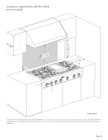
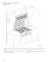
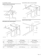
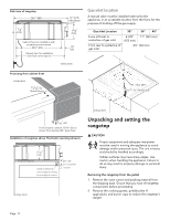
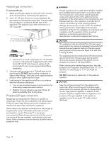
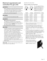
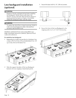
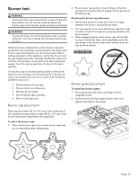
3. Leave protective film over brushed-metal surfaces, to protect finish from scratches, until the rangetop is installed in its final position. 4. Use a Phillips head screwdriver to remove the screws from the pallet brackets on the left and right sides of the unit. Discard the screws and brackets after removal. Setting the rangetop 5. Attach the backguard, if applicable, before sliding the appliance into the final installed position. (See "Low backguard installation (optional)" on page 15.) 6. Lift and place the rangetop in the countertop opening. Be careful not to pinch the power cord or gas inlet. Care should be used not to scratch the countertop. 7. Make sure that the power cord is free and hanging loose. 8. The rangetop must be level for proper performance. 9. Replace the cooking grates, griddle plate, and burner caps. Ensure that the burner caps are correctly seated on the burner bases. Assembling the griddle or grill (not all models) Refer to the Use and Care Guide. Gas requirements and hookup 9 CAUTION The appliance must be isolated from the gas supply piping system by closing its individual manual shut-off valve during any pressure testing of the gas supply piping system at test pressures equal to or less than 1/ 2 psig (3.5kPa.). 9 WARNING DO NOT use a flame of any kind to check for gas leaks. 9 CAUTION When connecting unit to propane gas, make certain the propane gas tank is equipped with its own high pressure regulator in addition to the pressure regulator supplied with the appliance. The pressure of the gas supplied to the appliance regulator must not exceed 14" water column (34.9 mb). IMPORTANT: Do not ground to a gas pipe. • Verify the type of gas being used at the installation site. Make certain the range matches the type of gas available at this location. • A metal flex line or fixed metal pipe shall be used to connect gas to the appliance. If a metal gas line cannot be used, consult your local certified electrician or local electric codes for proper grounding. • The gas supply connections shall be made by a competent technician and in accordance with local codes or ordinances. In the absence of local codes, the installation must conform to the National Fuel Gas Code ANSI Z223.1/NFPA54- current issue. • A manual gas shut-off valve must be installed external to the appliance, in a location accessible from the front, for the purpose of shutting off the gas supply. The supply line must not interfere with the back of the unit. Make sure the gas supply is turned off at the manual shut-off valve before connecting the appliance. • The installer should inform the owner of the location of the gas shut-off valve. Make sure all users know where and how to shut off the gas supply to the rangetop. High altitude This appliance has been tested for operation up to an altitude of 10,100 ft (3,078 m) elevation above sea level. A high altitude kit is required for natural gas above 5,400 feet (1,646 m) elevation above sea level, and for propane (LP) above 10,000 feet (3048 m) elevation above sea level. If desired, for altitudes above 2,000 feet (610 m) elevation above sea level, adjustments can be made to the rangetop burners with an adjustment kit. If flame performance is satisfactory, adjustment will not be required. It is required that a Certified Professional make the high altitude adjustments during installation. See the back cover for information about service, parts, and accessories. Gas requirements Natural gas requirements • Inlet connection: 1/2'' NPT internal (Minimum 3/4'' dia. flex line) • Supply pressure: 7'' min. to 14'' max. water column (17.4 to 34.9 mb) • Manifold pressure: 5'' water column (12.5 mb) Propane gas requirements • Inlet connection: 1/2'' NPT internal (minimum 3/4'' dia. flex line) • Supply pressure: 11'' min. to 14'' max. water column (27.4 mb to 34.9 mb) • Manifold pressure: 10'' water column (24.9 mb) Page. 12
-
 1
1 -
2
-
3
-
4
-
5
-
6
-
7
-
8
-
 9
9 -
 10
10 -
 11
11 -
 12
12 -
 13
13 -
 14
14 -
 15
15 -
 16
16 -
 17
17 -
 18
18 -
 19
19 -
20
-
21
-
22
-
23
-
24
-
25
-
26
-
27
-
28
-
29
-
30
-
31
-
32
-
33
-
34
-
35
-
36
-
37
-
38
-
39
-
40
-
41
-
42
-
43
-
44
-
45
-
46
-
47
-
48
-
49
-
50
-
51
-
52
-
53
-
54
-
55
-
56
-
57
-
58
-
59
-
60
 |
 |
