Thermador PCG364WL Installation Instructions - Page 13
Unpacking and setting the rangetop, Gas inlet location
 |
View all Thermador PCG364WL manuals
Add to My Manuals
Save this manual to your list of manuals |
Page 13 highlights
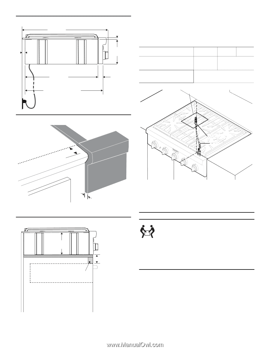
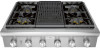
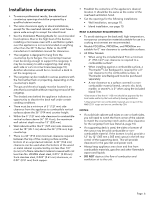
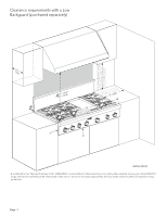
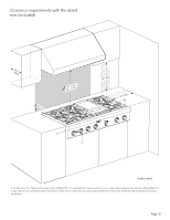
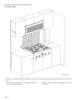
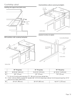
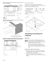
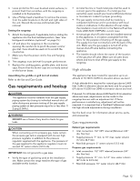
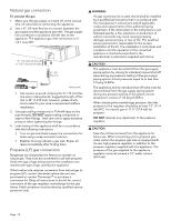
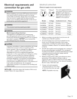
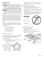
Side view of rangetop 26¾" (680) ½" (12.7) side flange 7/8" (22) 7 5/8" (194) Cabinet face for installation with projecting control panel. 22½" (573) 1½" (38) Cabinet face for installation with flush control panel. inches (mm) Gas inlet location A manual valve must be installed external to the appliance, in an accessible location from the front, for the purpose of shutting off the gas supply. Gas Inlet Location 30'' 36'' 48'' From left side to centerline of gas inlet 6-3/8'' 11" (267 mm) (152 mm) From rear to centerline of gas inlet 2¼'' (54 mm) Projecting from cabinet front inches (mm) 11/16" (18) Notch Depth ½" (12.7) NPT ¾" (19) flex line 13/16" (20) Front projects outward 13/16" (20) as shown from standard 24" deep base. Installation of rangetop above Thermador warming drawers 7 5/8" (194) Plywood support Install additional wood support along front edge of cutout 2¾" (70) min. between cutouts inches (mm) inches (mm) Unpacking and setting the rangetop 9 CAUTION Proper equipment and adequate manpower must be used in moving the appliance to avoid damage and/or personal injury. The unit is heavy and should be handled accordingly. Hidden surfaces may have sharp edges. Use caution when handling the appliance. Failure to do so may result in property damage or personal injury. Removing the rangetop from the pallet 1. Remove the outer carton and packing material from the shipping base. Ensure that you have all rangetop components before proceeding. 2. Remove the cooking grates, griddle plate (if applicable), and burner caps to reduce the rangetop's weight. Page. 11
-
 1
1 -
2
-
3
-
4
-
5
-
6
-
7
-
 8
8 -
 9
9 -
 10
10 -
 11
11 -
 12
12 -
 13
13 -
 14
14 -
 15
15 -
 16
16 -
 17
17 -
 18
18 -
19
-
20
-
21
-
22
-
23
-
24
-
25
-
26
-
27
-
28
-
29
-
30
-
31
-
32
-
33
-
34
-
35
-
36
-
37
-
38
-
39
-
40
-
41
-
42
-
43
-
44
-
45
-
46
-
47
-
48
-
49
-
50
-
51
-
52
-
53
-
54
-
55
-
56
-
57
-
58
-
59
-
60
 |
 |