Thermador PRG486WDH Installation Instructions - Page 23
Data rating label, Burner test
 |
View all Thermador PRG486WDH manuals
Add to My Manuals
Save this manual to your list of manuals |
Page 23 highlights
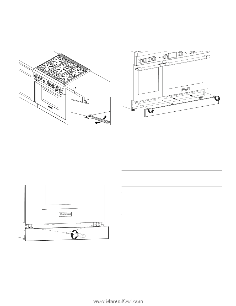
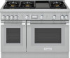
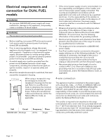
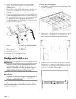
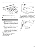
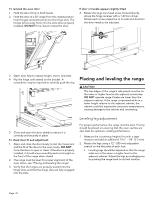
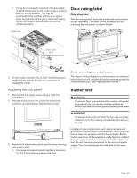
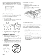
• It may be necessary to reposition the gas supply line and the electrical cord as the range is pushed back to its final position. This may be accomplished by carefully pulling on a rope or twine looped around the gas or electrical supply line as the range is pushed back into its final installed position. Data rating label Data rating label The data rating label shows the model and serial number of your appliance. The label can be accessed by first removing the kick panel, as shown below. inches (mm) 1/16''-1/8'' (2-3) 3. As the range is moved into its final, installed position, verify that the anti-tip bracket is in a position to engage the range. Adjusting the kick panel 1. Remove the kick panel screws using a T-20 torx screwdriver. 2. Relocate kick panel at one of the five screw hole positions, as noted below. Reinstall torx screw. Electric wiring diagrams and schematics The electric wiring diagrams and schematics are attached behind the toe kick, and should not be removed except by a service technician, then replaced after service. Burner test 9 WARNING To prevent flare-ups and avoid the creation of harmful by-products, do not use the cooktop without all burner caps and all burner grates properly positioned. 9 WARNING To prevent burns, do not touch burner caps or grates while hot. Turn the cooktop off and allow the burners to cool. 3. Repeat with the remaining kick panel screws, assuring kick panel is level. • The range kick panel should maintain a minimum ½'' (12.7 mm) clearance above the floor. Install any loose components, such as burner caps and grates that may have been removed earlier. Be certain that burner caps seat properly into the burner bases. Before testing operation of the appliance, verify that the unit and the gas supply have been carefully checked for leaks and that the unit has been connected to the electrical power supply. Turn the manual gas shut-off valve to the open position. Page. 22
-
 1
1 -
2
-
3
-
4
-
5
-
6
-
7
-
8
-
9
-
10
-
11
-
12
-
13
-
14
-
15
-
16
-
17
-
 18
18 -
 19
19 -
 20
20 -
 21
21 -
 22
22 -
 23
23 -
 24
24 -
 25
25 -
 26
26 -
 27
27 -
 28
28 -
29
-
30
-
31
-
32
-
33
-
34
-
35
-
36
-
37
-
38
-
39
-
40
-
41
-
42
-
43
-
44
-
45
-
46
-
47
-
48
-
49
-
50
-
51
-
52
-
53
-
54
-
55
-
56
-
57
-
58
-
59
-
60
-
61
-
62
-
63
-
64
-
65
-
66
-
67
-
68
-
69
-
70
-
71
-
72
-
73
-
74
-
75
-
76
-
77
-
78
 |
 |