Thermador UCVM30XS Installation Instructions - Page 19
Install the electrical panel
 |
View all Thermador UCVM30XS manuals
Add to My Manuals
Save this manual to your list of manuals |
Page 19 highlights
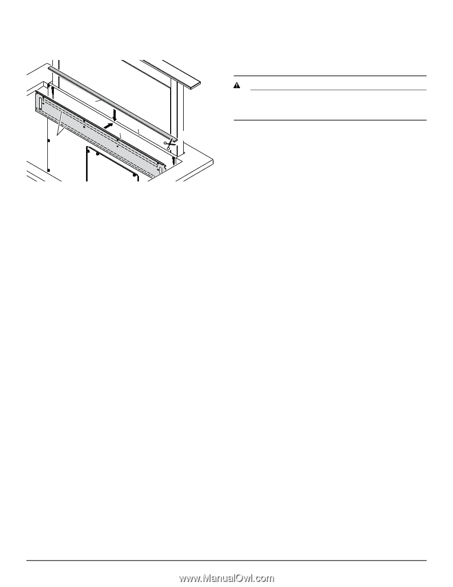
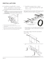
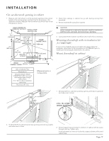
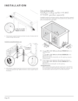
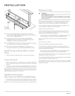
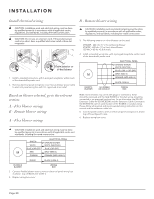
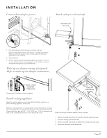
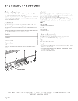
I N S TA L L AT I O N Plan house wiring E B E A G CD D F D Clean housing surface (B) with Isopropyl Alcohol or Rubbing Alcohol. Remove TAPE STRIPS to reveal adhesive side of tape from the back side of TRIM BRACKET (A). E Center trim bracket left-to-right at TOP OF DOWNDRAFT HOUSING (B). Stick trim bracket to downdraft housing so that FLANGES (C) and (D) are lush with each other. F Cut TRIM SEAL (E) to length: No shorter than downdraft countertop cutout opening and no longer than cooktop width. G Remove tape backing from TRIM SEAL (E). Center trim seal left-to-right and stick trim seal across both FLANGES (C) and (D). Install roof cap, wall cap, inline or remote blower 1. Follow instructions included with caps, inline and remote blower. Connect ductwork 1. From roof cap, wall cap, or remote blower - work back towards the cabinet, attaching all ductwork, elbows and transitions as previously planned. 2. Connect ductwork (and transition, if required) to lex blower or downdraft. If necessary, use (2) no. 8-18 x .375 (9.5 mm) Phillips screws for transition. Note: Regardless of blower placement/exhaust, ensure that all seams are properly taped - to make them secure and air-tight. This includes seams/ gaps between panels and/or on the blower. WARNING RISK OF ELECTRIC SHOCK Parts inside the appliance can have sharp edges. The connection cable can be damaged. Do not bend or pinch connection cables during installation. Before connecting the appliance, check the house wiring to make sure it has suficient circuit protection. The voltage and frequency of the appliance must match the electrical installation (see rating plate). Only a qualiied electrician who takes the appropriate regulations into account may lay or replace the connecting cable. Follow all valid standards and laws. Ensure that the electrical connection meets the requirements of the latest version of all applicable standards and laws in the appropriate country, especially the following standards: National Electrical Code, ANSI/ NFPA 70, or CSA Standards C22.1-94, Canadian Electrical Code, Part 1 and C22.2 No.0-M91, UL 507. Have a qualiied electrical technician check the grounding of the appliance. Do not ground to a gas line. Keep these installation instructions for future reference. Ensure that the wire diameter meets the requirements of the latest version of all applicable standards and laws in the appropriate country, especially the following standards: National Electrical Code, ANSI/NFPA 70, or CSA Standards C22.194, Canadian Electrical Code, Part 1 and C22.2 No.0-M91. The downdraft with the Flex Blower (purchase separately) draws 3.0 Amps and requires a 120 VAC, 60 Hz circuit. The downdraft with Remote Blower (purchase separately) draws 9.0 Amps (max.) and requires a 120 VAC, 60 Hz circuit. The downdraft has a 30-in. (762 mm). long power cord with a 3-pronged plug. Plan to provide a grounded outlet in a location which will allow the power cord to reach. Install the electrical panel (if previously removed from downdraft housing) 1. If electrical panel was removed from the downdraft housing in order to mount it in a remote location: Mount electrical panel in chosen location. Note: Do not mount electrical panel with slots in cover facing downward. Page 19
-
 1
1 -
2
-
3
-
4
-
5
-
6
-
7
-
8
-
9
-
10
-
11
-
12
-
13
-
 14
14 -
 15
15 -
 16
16 -
 17
17 -
 18
18 -
 19
19 -
 20
20 -
 21
21 -
 22
22 -
 23
23 -
 24
24 -
25
-
26
-
27
-
28
-
29
-
30
-
31
-
32
-
33
-
34
-
35
-
36
-
37
-
38
-
39
-
40
-
41
-
42
-
43
-
44
-
45
-
46
-
47
-
48
-
49
-
50
-
51
-
52
-
53
-
54
-
55
-
56
-
57
-
58
-
59
-
60
-
61
-
62
-
63
-
64
 |
 |