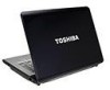
Toshiba A205-S7468 Maintenance Manual
Toshiba A205-S7468 - Satellite - Core 2 Duo 1.5 GHz Manual
 |
UPC - 032017977501
View all Toshiba A205-S7468 manuals
Add to My Manuals
Save this manual to your list of manuals |
Toshiba A205-S7468 manual content summary:
- Toshiba A205-S7468 | Maintenance Manual - Page 1
Toshiba Personal Computer Satellite A200 Maintenance Manual TOSHIBA CORPORATION [CONFIDENTIAL] - Toshiba A205-S7468 | Maintenance Manual - Page 2
use of the information contained herein. Toshiba Personal Computer Satellite A200 Maintenance Manual First edition March 2007 Disclaimer The information presented in this manual has been reviewed and validated for accuracy. The included set of instructions and descriptions are accurate for the A200 - Toshiba A205-S7468 | Maintenance Manual - Page 3
overheating, smoke or fire. ‰ If you replace the battery pack or RTC battery, be sure to use only the same model battery or an equivalent battery recommended by Toshiba. Installation of the wrong battery can cause the battery to explode. Satellite A200 Series Maintenance Manual [CONFIDENTIAL] iii - Toshiba A205-S7468 | Maintenance Manual - Page 4
following parts: Chapter 1 Hardware Overview describes the M100 Series system unit and each FRU. Chapter 2 Troubleshooting Procedures explains how to diagnose and resolve FRU problems. Chapter 3 Test and Diagnostics describes how to perform test and diagnostic operations for maintenance service - Toshiba A205-S7468 | Maintenance Manual - Page 5
(Break). If three keys are used, hold down the first two and at the same time press the third. User input Text that you are instructed to type in is shown in the boldface type below: DISKCOPY A: B: The display Text generated by the computer that appears on its display is presented - Toshiba A205-S7468 | Maintenance Manual - Page 6
1.3 2.5-inch Hard Disk Drive 1-6 1.4 Optical device Drives ...1-8 1.5 Power Supply ...1-10 1.6 Batteries...1-12 Chapter 2 Troubleshooting Procedures 2.1 Troubleshooting Introduction 2-3 2.2 Troubleshooting Flowchart 2-Error! Bookmark not defined. 2.3 Power Supply Troubleshooting 2-9 2.4 Display - Toshiba A205-S7468 | Maintenance Manual - Page 7
LAN Test 3-21 3.14 RTC Test 3-24 3.15 Read 1394 GUID 3-25 3.16 Speaker EQ Type Check&Re-Write 3-26 3.17 Button Test 3-27 3.18 1st HDD Test 3-28 3.19 2nd HDD Test 3-31 3.20 Satellite LED Test 3-34 Chapter 4 Replacement Procedures 4.1 General Error ! Bookmark not defined. 4.2 Battery - Toshiba A205-S7468 | Maintenance Manual - Page 8
4.6 Expansion Memory Error! Bookmark not defined. 4.7 Optical Drive Module Error! Bookmark not defined. 4.8 Optical Drive Error! Bookmark Error! Bookmark not defined. 4.16 Bluetooth module Error! Bookmark not defined. viii [CONFIDENTIAL] Satellite A200 Series Maintenance Manual - Toshiba A205-S7468 | Maintenance Manual - Page 9
4.22 MDC Card Error! Bookmark not defined. 4.23 Wireless Module Error! Bookmark not defined. 4.24 System Fan Error! Bookmark not defined. 4.25 System Board Error! A-1 Appendix B Board Layout ...B-1 Appendix C Pin Assignments C-1 Satellite A200 Series Maintenance Manual [CONFIDENTIAL] ix - Toshiba A205-S7468 | Maintenance Manual - Page 10
Appendix D Keyboard Scan/Character Codes D-1 Appendix E Key Layout ...E-1 Appendix F Series Screw Torque List F-1 Appendix G Reliability ...G-1 x [CONFIDENTIAL] Satellite A200 Series Maintenance Manual - Toshiba A205-S7468 | Maintenance Manual - Page 11
Chapter 1 Hardware Overview 1 [CONFIDENTIAL] - Toshiba A205-S7468 | Maintenance Manual - Page 12
1 Hardware Overview 1-ii Minnesota 10M/10MG Series Maintenance Manual - Toshiba A205-S7468 | Maintenance Manual - Page 13
1 Hardware Overview Chapter 1 Contents 1.1 Features ...1-1 1.2 System Unit...1-5 1.3 2.5-inch Hard Disk Drive 1-6 1.4 Optical device Drives 1-8 1.5 Power Supply ...1-10 1.6 Batteries ...1-12 Minnesota 10M/10MG Series Maintenance Manual 1-iii - Toshiba A205-S7468 | Maintenance Manual - Page 14
Figures Figure 1-1 2.5-inch HDD 1-6 Tables Table 1-1 Table 1-2 Table 1-3 Table 1-4 2.5-inch HDD specifications 1-6 DVD-ROM & CD-RW drive specifications 1-8 DVD Super Multi Double Layer drive specifications 1-9 Battery specifications 1-12 1-iv Minnesota 10M/10MG Series Maintenance Manual - Toshiba A205-S7468 | Maintenance Manual - Page 15
Disk • Password protection - Power on password - Supervisor password - HDD password for WW - No HDD password for JP • Various hot key for system control • Refreshable • Complete ACPI 2.0 function • SMBIOS V2.4 • Supports JSB memory Boot, USB Super Fetch, SD Super Fetch ‰ Power • Universal AC adapter - Toshiba A205-S7468 | Maintenance Manual - Page 16
, DVD Super-multi device with Label Flash ‰ Optional Devices • Express Card • Build-in antenna for wireless LAN module • Build-in antenna for Bluetooth module • MDC Modem ‰ Keyboard • 86/87 keys • Standard pitch 19.05mm, 2.5±0.3mm travel length • Windows key, Application key • Vista key supported - Toshiba A205-S7468 | Maintenance Manual - Page 17
for wireless LAN communication • WLAN module b/g, a/b/g, and a/b/g/n ‰ 5 in 1 Card Reader Organization • TI 8402 controller • SD, miniSD, MMC, Memory Stick/PRO, and xD card supported • ACPI 2.0 compliant ‰ Excellent Power Management Function • Standby mode, Suspend to RAM or Suspend to disk mode - Toshiba A205-S7468 | Maintenance Manual - Page 18
1.1 Features ‰ Switches • Power button • Two programmable launch buttons • Four control buttons for CD playing • Wireless communication switch ‰ Security • Fingerprint authentication ‰ AC Adapter • Universal AC adapter module • Liteon & Delta 65W, 75W and 90W adapters • Output voltage: 19Vdc - Toshiba A205-S7468 | Maintenance Manual - Page 19
945PM with ICH7M Chipset • Mobile Intel® 943GML with ICH7M Chipset ‰ Memory • Two DDR-II 533/667MHz SO-DIMM • Supports Dual channel • Up to 2GB with 256MB/512MB/1GB module for control, rotary type, without mute function − Supports Microsoft Outlook Express audio Minnesota 10M/10MG Series Maintenance - Toshiba A205-S7468 | Maintenance Manual - Page 20
1.3 2.5-inch Hard Disk Drive 1.3 2.5-inch Hard Disk Drive The internal HDD is a random access non-volatile storage device. It has a non-removable 2.5-inch magnetic disk and mini-Winchester type magnetic heads. The computer supports up to 250G HDD. The HDD is shown in Figure 1-1. Specifications are - Toshiba A205-S7468 | Maintenance Manual - Page 21
1.3 2.5-inch Hard Disk Drive 1 Hardware Overview Items 120GB 160GB 200GB 250GB Formatted capacity (GB) Logical Blocks (LBA) Rotational speed (rpm) Toshiba HDD Buffer (MB) Hitachi N/A N/A 8 512 Table 1-1 2.5-inch HDD specifications (Continued) Minnesota 10M/10MG Series Maintenance Manual 1-7 - Toshiba A205-S7468 | Maintenance Manual - Page 22
Average random access 150 130 Data buffer size (Mbytes) 2MB DVD: DVD-VIDEO, DVD-ROM Formats supported CD: CD-DA, CD-ROM, CD-R, CD-RW, CD-ROMXA, PhotoCD (single/multi-session), CD-EXTRA, CD-Text Table 1-2 DVD-ROM & CD-RW drive specifications 1-8 Minnesota 10M/10MG Series Maintenance Manual - Toshiba A205-S7468 | Maintenance Manual - Page 23
supported DVD-VIDEO, DVD-ROM, DVD-R, DVD-RW, DVD-RAM, DVD+R, DVD+RW, DVD+R DL, DVD-R DL CD: CD-DA, CD-ROM, CD-R, CD-RW, CD-ROMXA, PhotoCD (single/multi-session), CD-EXTRA, CD-Text Table 1-3 DVD Super Multi Double Layer drive specifications Minnesota 10M/10MG Series Maintenance Manual 1-9 - Toshiba A205-S7468 | Maintenance Manual - Page 24
- DC IN LED (one color: blue) • Blue: indicates AC adapter is connected - Battery LED (two colors: orange and blue) • Blue solid: The battery is fully charged. • Orange: The computer is quick-charging the battery / the battery is low. ‰ Power ON/OFF sequence • When power is turned on or off, the EC - Toshiba A205-S7468 | Maintenance Manual - Page 25
detection of full charge ‰ Detection of the low battery • The EC detects the low battery point by the gas gauge. - LB10M: The system will be driven by the battery for 12 more minutes. - LB0: The battery won't be able to drive the system after 3 minutes. - LB1: The battery can drive the system only - Toshiba A205-S7468 | Maintenance Manual - Page 26
has two types of battery: ‰ Main battery pack (18650 size) ‰ RTC battery The removable main battery pack is the computer's main power source when the AC adapter is not attached. The battery specifications are listed in the table below. Battery name Material Main battery (3 cells) Lithium-Ion - Toshiba A205-S7468 | Maintenance Manual - Page 27
and detects a full charge when the AC adapter and battery are attached to the computer. The system charges the battery using quick charge or trickle charge. ‰ Quick Battery Charge When the AC adapter is attached, there are two types of quick charges: quick charge when the system is powered off and - Toshiba A205-S7468 | Maintenance Manual - Page 28
other setup information in memory while the computer is turned off. The table below lists the charging time and data preservation period of the RTC battery. The RTC battery is charged by the adapter or main battery, while the computer is powered on. Status Charging Time (power on) Data preservation - Toshiba A205-S7468 | Maintenance Manual - Page 29
Chapter 2 Troubleshooting Procedures 2 - Toshiba A205-S7468 | Maintenance Manual - Page 30
- Toshiba A205-S7468 | Maintenance Manual - Page 31
2.13 IEEE 1394 Troubleshooting 35 2.14 Wireless LAN Troubleshooting 37 2.15 Camera Troubleshooting 39 2.16 Bluetooth Troubleshooting 41 2.17 4 in 1 card Troubleshooting 43 2.18 1st HDD Troubleshooting 45 2.19 2nd HDD Troubleshooting 48 Satellite A200/A205/Pro A200 Series Maintenance Manual - Toshiba A205-S7468 | Maintenance Manual - Page 32
Wireless LAN troubleshooting process 36 Camera troubleshooting process 38 Bluetooth troubleshooting process 40 4 in 1 card troubleshooting process 42 1st HDD troubleshooting process 44 2nd HDD troubleshooting process 45 Tables Table 2-1 Battery LED ...10 Table 2-2 DC-IN LED ...11 Satellite - Toshiba A205-S7468 | Maintenance Manual - Page 33
IEEE 1394 port 2. USB Floppy Drive 7. Speaker 12. Wireless LAN system 3. Keyboard 8. Optical drive 13. Camera 4. USB ports 9. Modem 14. Bluetooth 5. TV-out port 10. EXPRESS CARD unit The Diagnostics Disk operations are described in Chapter 3. Detailed replacement procedures are given in - Toshiba A205-S7468 | Maintenance Manual - Page 34
to execute. Before performing any troubleshooting procedures, verify the following: z Ask the user if a password is registered and, if it is, ask him or her to enter the password. z Verify with the customer that Toshiba Windows Vista is installed on the hard disk. Operating systems that were not - Toshiba A205-S7468 | Maintenance Manual - Page 35
displays, type the passw ord, then press Enter. Is Toshiba W indow s being loaded? Y es A Perform diagnostics program . No R un C M 165.EX E and select the H ARD D ISK item . Figure 2-1 Troubleshooting flowchart (1/2) Satellite A200/A205/Pro A200 Series Maintenance Manual [CONFIDENTIAL] 5 - Toshiba A205-S7468 | Maintenance Manual - Page 36
FDD No Troubleshooting procedures in section 2.5 After confirming which diagnostics test has detected Yes an error, perform the appropriate procedure as outlined below. End Figure 2-1 Troubleshooting flowchart (2/2) Satellite A200/A205/Pro A200 Series Maintenance Manual [CONFIDENTIAL] 6 - Toshiba A205-S7468 | Maintenance Manual - Page 37
the Speaker Troubleshooting procedures in Section 2.9 and the Optical Drive Troubleshooting Procedures in Section 2.10. 6. If an error is detected by the modem test, perform the Modem Troubleshooting Procedures in Section 2.11. Satellite A200/A205/Pro A200 Series Maintenance Manual [CONFIDENTIAL - Toshiba A205-S7468 | Maintenance Manual - Page 38
using the IEEE1394 device, perform the IEEE1394 device Troubleshooting procedures in Section 2.13. 7. If an error is detected when using the Wireless LAN, perform the Wireless LAN Troubleshooting procedures in Section 2.14. Satellite A200/A205/Pro A200 Series Maintenance Manual [CONFIDENTIAL] 8 - Toshiba A205-S7468 | Maintenance Manual - Page 39
/ battery (Procedure 2) Can you turn the computer on? No Are the internal power connections secure? Y es Replace system board Y es Run diagnostic program (Procedure 4) Perform internal connection No check (Procedure 5) END Figure 2-2 Power Supply Troubleshooting Process Satellite A200/A205 - Toshiba A205-S7468 | Maintenance Manual - Page 40
on for 1 second minutes remaining. The system is every 2 seconds) protected and cannot be re-powered on without the AC power connected. Amber color off Battery not in low or critical low state; It's in discharging state Satellite A200/A205/Pro A200 Series Maintenance Manual 10 [CONFIDENTIAL] - Toshiba A205-S7468 | Maintenance Manual - Page 41
/ battery replacement A faulty adaptor may not supply power or may not charge the battery. Perform Check 1. Check 1 Connect a new AC adaptor. If the problem is not resolved, go to Check 2. Check 2 Insert a new battery. If the problem is still not resolved, go to Procedure 3. Satellite A200/A205/Pro - Toshiba A205-S7468 | Maintenance Manual - Page 42
2 Troubleshooting Procedures Procedure 3 Power supply connection check The power supply wiring diagram is shown below: AC power cord AC adaptor AC adaptor cord System board Battery Any of the connectors may be disconnected. Perform Check 1. Check 1 Disconnect the AC power cord from wall - Toshiba A205-S7468 | Maintenance Manual - Page 43
2 Make sure that the battery cable is firmly connected to the system board. If it is connected firmly, go to Check 3. Check 3 The system board may be damaged. Replace it with a new one following the instructions in Chapter 4. Satellite A200/A205/Pro A200 Series Maintenance Manual 13 [CONFIDENTIAL] - Toshiba A205-S7468 | Maintenance Manual - Page 44
display problem detected? D isplay is not No faulty. C ontinue tro u b le sh o o tin g - refer to Figure 2.1 Y es Perform connector and replacem ent check (Procedure 3) R eplace system board END Figure 2-3 Display troubleshooting process Satellite A200/A205/Pro A200 Series Maintenance Manual - Toshiba A205-S7468 | Maintenance Manual - Page 45
's floppy disk drive, turn on the computer and run the test. Refer to Chapter 3, Tests and Diagnostics for details. If an error is detected, go to Procedure 3. If an error is not detected, the display is functioning properly. Satellite A200/A205/Pro A200 Series Maintenance Manual 15 [CONFIDENTIAL - Toshiba A205-S7468 | Maintenance Manual - Page 46
. If the problem still exists, perform Check 5. Check 5 Replace the CPU with another of the same specifications. If the problem still exists, perform Check 6. Check 6 The system board may be damaged. Replace it with a new one. Satellite A200/A205/Pro A200 Series Maintenance Manual 16 [CONFIDENTIAL - Toshiba A205-S7468 | Maintenance Manual - Page 47
problem detected? K eyboard is not No faulty. C ontinue tro u b le sh o o tin g - refer to Figure 2.1 Y es Perform connector and replacem ent check (Procedure 3) R eplace system board END Figure 2-4 Keyboard troubleshooting process Satellite A200/A205/Pro A200 Series Maintenance Manual - Toshiba A205-S7468 | Maintenance Manual - Page 48
may be damaged. Replace it with a new one following the instructions in Chapter 4. If the problem still exists, perform Check 3. Check 3 The system board may be damaged. Replace it with a new one following the instructions in Chapter 4. Satellite A200/A205/Pro A200 Series Maintenance Manual 18 - Toshiba A205-S7468 | Maintenance Manual - Page 49
Procedures 2.6 External USB Devices Troubleshooting START Perform external device and connection check (Procedure 1) Check U SB port c o n board (Procedure 2) END Figure 2-5 External USB device troubleshooting process Satellite A200/A205/Pro A200 Series Maintenance Manual 19 [CONFIDENTIAL] - Toshiba A205-S7468 | Maintenance Manual - Page 50
same problem as the original device, the system board may be damaged. Go to Procedure 2. Procedure 2 Replace system board If the error persists, the system board may be damaged. Replace it with a new one following the instructions in Chapter 4. Satellite A200/A205/Pro A200 Series Maintenance Manual - Toshiba A205-S7468 | Maintenance Manual - Page 51
T V cable function properly? No Perform T V set check (Procedure 2) No R eplace T V cable T V functioning ok? Y es R eplace system board END No U se different T V set Figure 2-6 TV-out troubleshooting process Satellite A200/A205/Pro A200 Series Maintenance Manual 21 [CONFIDENTIAL] - Toshiba A205-S7468 | Maintenance Manual - Page 52
to the computer. If the replacement television works, the original set may be damaged. If the replacement set does not work the system board may be damaged. Replace it with a new one following the instructions in Chapter 4. Satellite A200/A205/Pro A200 Series Maintenance Manual 22 [CONFIDENTIAL] - Toshiba A205-S7468 | Maintenance Manual - Page 53
2 Troubleshooting Procedures 2.8 TouchPad Troubleshooting START TouchPad connection check (Procedure 1) TouchPad replacement check (Procedure 2) Replace system board END Figure 2-7 Touchpad troubleshooting process Satellite A200/A205/Pro A200 Series Maintenance Manual 23 [CONFIDENTIAL] - Toshiba A205-S7468 | Maintenance Manual - Page 54
to Chapter 4, Replacement Procedures, for instructions on how Replace each with a new one following the steps in Chapter 4. If the FDD is still not functioning properly, replace the system board with a new one following the steps in Chapter 4. Satellite A200/A205/Pro A200 Series Maintenance Manual - Toshiba A205-S7468 | Maintenance Manual - Page 55
. Continue troubleshooting - see Figure 2-1 Do earphones function correctly? Yes Perform connection check No (Procedure 3) Perform replacement check (Procedure 4) Replace system board END Figure 2-8 Speaker troubleshooting process Satellite A200/A205/Pro A200 Series Maintenance Manual - Toshiba A205-S7468 | Maintenance Manual - Page 56
sources have sound problem, the problem is in the source devices. If all have the same problem, continue with Replace them with new ones. If the stereo speakers still do not work properly, try replacing in turn the audio board and system board. Satellite A200/A205/Pro A200 Series Maintenance Manual - Toshiba A205-S7468 | Maintenance Manual - Page 57
(Procedure 2) Yes Perform software check (Procedure 3) Perform diagnostic test (Procedure 4) Perform connection and replacement check (Procedure 5) Replace system board END Figure 2-9 Optical drive troubleshooting process Satellite A200/A205/Pro A200 Series Maintenance Manual [CONFIDENTIAL] 27 - Toshiba A205-S7468 | Maintenance Manual - Page 58
2 Troubleshooting Procedures This section describes how to determine if the computer's internal optical drive is functioning properly. The Satellite A200/Satellite A205/Satellite Pro A200/EQUIUM A200/SATEGO A200 module bays can accommodate the following optical drives: DVD SuperMulti supporting +-R - Toshiba A205-S7468 | Maintenance Manual - Page 59
Chapter 4, Replacement Procedures. If the drive is still not functioning properly, perform Check 3. Check 3 The system board may be damaged. Replace it with new one following the instructions in Chapter 4, Replacement Procedures. Satellite A200/A205/Pro A200 Series Maintenance Manual [CONFIDENTIAL - Toshiba A205-S7468 | Maintenance Manual - Page 60
telephone signal? Check / replace Yes telephone line and connections No Perform connection check (Procedure 2) Perform replacement check (Procedure 3) Replace system board END Figure 2-10 Modem troubleshooting process Satellite A200/A205/Pro A200 Series Maintenance Manual [CONFIDENTIAL] 30 - Toshiba A205-S7468 | Maintenance Manual - Page 61
telephone cable is firmly plugged into both the telephone replacing them. If the problem persists, the system board may be defective or damaged. Replace the System Board with a new one following the steps in Chapter 4, Replacement Procedures. Satellite A200/A205/Pro A200 Series Maintenance Manual - Toshiba A205-S7468 | Maintenance Manual - Page 62
1) D o errors occur during Express card test? Express card unit No is not faulty. Y es Perform Express card socket replacem ent check (Procedure 2) Replace system board END Figure 2-11 Express card troubleshooting process Satellite A200/A205/Pro A200 Series Maintenance Manual [CONFIDENTIAL] 32 - Toshiba A205-S7468 | Maintenance Manual - Page 63
steps described in Chapter 4, Replacement Procedures and replace the socket. If the problem persists, the system board may be defective or damaged. Replace the system board with a new one following the steps in Chapter 4. Satellite A200/A205/Pro A200 Series Maintenance Manual [CONFIDENTIAL] 33 - Toshiba A205-S7468 | Maintenance Manual - Page 64
IEEE 1394 problem detected? transmission are not No faulty. Continue troubleshooting - refer to Figure 2.1 Yes Perform connection and replacement check (Procedure 3) Replace system board END Figure 2-12 IEEE 1394 troubleshooting process Satellite A200/A205/Pro A200 Series Maintenance Manual - Toshiba A205-S7468 | Maintenance Manual - Page 65
Check 3 The transmission cable may be damaged. Replace with a good cable. If the malfunction persists, go to Check 4 Check 4 The system board may be damaged. Replace it with a new one following the instructions in Chapter 4. Satellite A200/A205/Pro A200 Series Maintenance Manual [CONFIDENTIAL] 35 - Toshiba A205-S7468 | Maintenance Manual - Page 66
check (Procedure 2) Wireless LAN system No is not faulty. Continue troubleshooting - refer to Figure 2.1 Replace wireless LAN antenna/unit Replace system board END Figure 2-13 Wireless LAN troubleshooting process Satellite A200/A205/Pro A200 Series Maintenance Manual [CONFIDENTIAL] 36 - Toshiba A205-S7468 | Maintenance Manual - Page 67
Check 3 The wireless LAN unit may be damaged. Replace it with a new one following the instructions in Chapter 4. If the problem still exists, perform Check 4. Check 4 The system board may be damaged. Replace it with a new one following the instructions in Chapter 4. Satellite A200/A205/Pro A200 - Toshiba A205-S7468 | Maintenance Manual - Page 68
2 Troubleshooting Procedures 2.15 Camera Troubleshooting Figure 2-14 Camera troubleshooting process Satellite A200/A205/Pro A200 Series Maintenance Manual [CONFIDENTIAL] 38 - Toshiba A205-S7468 | Maintenance Manual - Page 69
damaged. Replace it with a new one following the instructions in Chapter 4. If the problem still exists, perform Check 3. Check 3 The system board may be damaged. Replace it with a new one following the instructions in Chapter 4. Satellite A200/A205/Pro A200 Series Maintenance Manual [CONFIDENTIAL - Toshiba A205-S7468 | Maintenance Manual - Page 70
problem detect? Bluetooth isnot faulty. Continue troubleshooting-refer to Figure2.1 Performconnector and replacement check (Procedure 2) Replace Bluetooth antenna moudle. Replace system board END Figure 2-15 Bluetooth troubleshooting process Satellite A200/A205/Pro A200 Series Maintenance Manual - Toshiba A205-S7468 | Maintenance Manual - Page 71
3. Check 3 The Bluetooth module may be damaged. Replace it with a new one following the instructions in Chapter 4. If the problem still exists, perform Check 4. Check 4 The system board may be damaged. Replace it with a new one following the instructions in Chapter 4. Satellite A200/A205/Pro A200 - Toshiba A205-S7468 | Maintenance Manual - Page 72
1) Do errors occur during 4 IN 1 CARD test? 4 IN 1 unit is not No faulty. Yes Perform 4 IN 1 card socket replacement check (Procedure 2) Replace system board END Figure 2-16 4 in 1 card troubleshooting process Satellite A200/A205/Pro A200 Series Maintenance Manual [CONFIDENTIAL] 42 - Toshiba A205-S7468 | Maintenance Manual - Page 73
steps described in Chapter 4, Replacement Procedures and replace the socket. If the problem persists, the system board may be defective or damaged. Replace the system board with a new one following the steps in Chapter 4. Satellite A200/A205/Pro A200 Series Maintenance Manual [CONFIDENTIAL] 43 - Toshiba A205-S7468 | Maintenance Manual - Page 74
2 Troubleshooting Procedures 2.18 1st HDD Troubleshooting Figure 2-17 HDD troubleshooting process Satellite A200/A205/Pro A200 Series Maintenance Manual [CONFIDENTIAL] 44 - Toshiba A205-S7468 | Maintenance Manual - Page 75
. Replace it with a new one following the instructions in Chapter 4. If the problem still exists, perform Check 3. Check 3 The system board may be damaged. Replace it with a new one following the instructions in Chapter 4. Satellite A200/A205/Pro A200 Series Maintenance Manual [CONFIDENTIAL - Toshiba A205-S7468 | Maintenance Manual - Page 76
2 Troubleshooting Procedures Satellite A200/A205/Pro A200 Series Maintenance Manual [CONFIDENTIAL] 46 - Toshiba A205-S7468 | Maintenance Manual - Page 77
2 Troubleshooting Procedures 2.19 2nd HDD Troubleshooting Figure 2-18 2nd HDD troubleshooting process Satellite A200/A205/Pro A200 Series Maintenance Manual [CONFIDENTIAL] 47 - Toshiba A205-S7468 | Maintenance Manual - Page 78
. Replace it with a new one following the instructions in Chapter 4. If the problem still exists, perform Check 3. Check 3 The system board may be damaged. Replace it with a new one following the instructions in Chapter 4. Satellite A200/A205/Pro A200 Series Maintenance Manual [CONFIDENTIAL - Toshiba A205-S7468 | Maintenance Manual - Page 79
3. Tests and Diagnostics Chapter 3 Tests and Diagnostics 3 Satellite A205/A200 /Satellite Pro A200/EQUIUM A200/ SATEGO A200 Series Maintenance Manual 3-1 - Toshiba A205-S7468 | Maintenance Manual - Page 80
19 3.13 LAN Test...3-20 3.14 RTC Test ...3-23 3.15 Read 1394 GUID...3-24 3.16 Speaker EQ Check 3-25 3.17 Button Test 3-26 3.18 1st HDD Test...3-27 3.19 2nd HDD Test 3-30 3.20 Satellite LED test 3-34 3-2 Satellite A205/A200 /Satellite Pro A200/EQUIUM A200/ SATEGO A200 Series Maintenance Manual - Toshiba A205-S7468 | Maintenance Manual - Page 81
‰ FAN ON/OFF TEST ‰ MAIN BATTERY CHARGE TEST ‰ FDD TEST ‰ ODD TEST ‰ KEYBOARD TEST ‰ MOUSE(PAD) TEST ‰ LCD PIXELS MODE TEST ‰ MAGNETIC SWITCH TEST ‰ LAN TEST ‰ RTC TEST ‰ IEEE1394 CODE TEST ‰ Speaker EQ Check & Rewrite ‰ Button Test ‰ 1st HDD TEST ‰ 2nd HDD Test ‰ Satellite LED Test Satellite A205 - Toshiba A205-S7468 | Maintenance Manual - Page 82
disk drive test (Floppy Disk Drive Test) ‰ A data CD disc (ODD Test) ‰ A LAN loopback The following sections explain how to execute the Test & Diagnostic Program and detail the tests within the program. 3-4 Satellite A205/A200 /Satellite Pro A200/EQUIUM A200/ SATEGO A200 Series Maintenance Manual - Toshiba A205-S7468 | Maintenance Manual - Page 83
C. FAN ON/OFF TEST D. MAIN BATTERY TEST E. FDD TEST F. ODD TEST G. KEYBOARD TEST H. MOUSE (PAD) TEST I. LCD PIXELS MODE TEST J. MAGNETIC TEST K. LAN TEST L. RTC TEST M. IEEE1394 CODE TEST N. SPEAKER EQ CHECK TEST O. BUTTON TEST P. 1st HDD TEST Q. 2nd HDD TEST R. Satellite LED Test Satellite A205 - Toshiba A205-S7468 | Maintenance Manual - Page 84
3. Tests and Diagnostics The below display will show up at the beginning of T&D program If the test result passes, the following display will show up: 3-6 Satellite A205/A200 /Satellite Pro A200/EQUIUM A200/ SATEGO A200 Series Maintenance Manual - Toshiba A205-S7468 | Maintenance Manual - Page 85
key for next actions - the below display presented if copying test log file onto diskette is necessary. This action will be executed when "Y" key pressed. Satellite A205/A200 /Satellite Pro A200/EQUIUM A200/ SATEGO A200 Series Maintenance Manual 3-7 - Toshiba A205-S7468 | Maintenance Manual - Page 86
it's necessary to leave this program. Program will quit when "Y" key pressed and it will go back main menu for next test if "N" key pressed. 3-8 Satellite A205/A200 /Satellite Pro A200/EQUIUM A200/ SATEGO A200 Series Maintenance Manual - Toshiba A205-S7468 | Maintenance Manual - Page 87
HDD type & capacity (Vendor ID. Model .Firmware) Š VRAM size / VGA CHIP TYPE Š Battery cell (6cell;9cell;12cell) Š Wireless type Š LAN Type Š 1394 Š Bluetooth Š SKU ID The screen should display as below: Satellite A205/A200 /Satellite Pro A200/EQUIUM A200/ SATEGO A200 Series Maintenance Manual 3-9 - Toshiba A205-S7468 | Maintenance Manual - Page 88
volume as "Maximum" before this test starts. The screen should display as below, indicating whether the test is passed or failed after the question. 3-10 Satellite A205/A200 /Satellite Pro A200/EQUIUM A200/ SATEGO A200 Series Maintenance Manual - Toshiba A205-S7468 | Maintenance Manual - Page 89
the fan working after any key pressed. Feel the wind or listen the sound to check if the fan is "OFF". The screen should display as below, indicating whether the test is passed or failed after the question. Satellite A205/A200 /Satellite Pro A200/EQUIUM A200/ SATEGO A200 Series Maintenance Manual - Toshiba A205-S7468 | Maintenance Manual - Page 90
- "Battery Is Full" showed when "remain charge capacities" is 100% The screen should display as below, if the charge function is OK, will show:. If the charge function is NG, the screen will display as: 3-12 Satellite A205/A200 /Satellite Pro A200/EQUIUM A200/ SATEGO A200 Series Maintenance Manual - Toshiba A205-S7468 | Maintenance Manual - Page 91
diskette into the FDD. The contents of the floppy diskette maybe erased. The Floppy Disk Test includes three subtests of the: 1. Sequential seek/verify function (Range: Track 0 or fail when finished. Satellite A205/A200 /Satellite Pro A200/EQUIUM A200/ SATEGO A200 Series Maintenance Manual 3-13 - Toshiba A205-S7468 | Maintenance Manual - Page 92
aurally confirm the ODD functions. NOTE: A CD disc (including data file) must be inserted into the ODD drive then must wait ODD drive initial OK (ODD LED stop flashing) before this or fail when finished. 3-14 Satellite A205/A200 /Satellite Pro A200/EQUIUM A200/ SATEGO A200 Series Maintenance Manual - Toshiba A205-S7468 | Maintenance Manual - Page 93
test. To determine whether the "Fn" key is working correctly, press "Fn+F6 " or "Fn+F7 " keys to check if LCD display brightness change gradually. Satellite A205/A200 /Satellite Pro A200/EQUIUM A200/ SATEGO A200 Series Maintenance Manual 3-15 - Toshiba A205-S7468 | Maintenance Manual - Page 94
the Touch Pad or "Tab" key to move between selections: 1. Mouse Speed (on a scale from slow to fast) 2. Acceleration (Off, Low, Medium, High) 3. Button Assignments (Left + Right / the screen as below. 3-16 Satellite A205/A200 /Satellite Pro A200/EQUIUM A200/ SATEGO A200 Series Maintenance Manual - Toshiba A205-S7468 | Maintenance Manual - Page 95
although the Touch Pad installed may only have two buttons. In this case, the central compartment in the figure does not correspond to any button. Satellite A205/A200 /Satellite Pro A200/EQUIUM A200/ SATEGO A200 Series Maintenance Manual 3-17 - Toshiba A205-S7468 | Maintenance Manual - Page 96
(256 colors) and 1024*768 (256 colors). The screen should display as below, indicating whether the test is passed or failed after the question. 3-18 Satellite A205/A200 /Satellite Pro A200/EQUIUM A200/ SATEGO A200 Series Maintenance Manual - Toshiba A205-S7468 | Maintenance Manual - Page 97
: 1. Close the LCD cover. 2. Heard 3 "Beep" sound happened during LCD closed. 3. Open the LCD. Then it will indicate whether the test is passed or failed. Satellite A205/A200 /Satellite Pro A200/EQUIUM A200/ SATEGO A200 Series Maintenance Manual 3-19 - Toshiba A205-S7468 | Maintenance Manual - Page 98
Line Frame - 1514 Bytes. Š Line Speed - 100Mbps or 10 Mbps. Š Bus ID - it's "4". The LAN test includes three subtests of the: 1. Speed1000 2. Speed100 3. Speed10 The subtests run automatically. 3-20 Satellite A205/A200 /Satellite Pro A200/EQUIUM A200/ SATEGO A200 Series Maintenance Manual - Toshiba A205-S7468 | Maintenance Manual - Page 99
3. Tests and Diagnostics The screen should display as below, indicating whether the subtests pass or fail when finished. Satellite A205/A200 /Satellite Pro A200/EQUIUM A200/ SATEGO A200 Series Maintenance Manual 3-21 - Toshiba A205-S7468 | Maintenance Manual - Page 100
3. Tests and Diagnostics If an error is detected and a test fails, the following message displays: 3-22 Satellite A205/A200 /Satellite Pro A200/EQUIUM A200/ SATEGO A200 Series Maintenance Manual - Toshiba A205-S7468 | Maintenance Manual - Page 101
the DOS and CMOS values. The test runs automatically. The screen should display as below, indicating whether the test is passed or failed when finished. Satellite A205/A200 /Satellite Pro A200/EQUIUM A200/ SATEGO A200 Series Maintenance Manual 3-23 - Toshiba A205-S7468 | Maintenance Manual - Page 102
GUID This test will check if the computer's EEPROM 1394GUID code is correct. NOTE: Must open the RAM Door to see RAM connector GUID bar code before test item begins. The figure below will be displayed: 3-24 Satellite A205/A200 /Satellite Pro A200/EQUIUM A200/ SATEGO A200 Series Maintenance Manual - Toshiba A205-S7468 | Maintenance Manual - Page 103
-Write EQ Type to EEPROM NOTE: To execute this test, you must select speaker type (Harman or No brand). The figure below will be displayed: Satellite A205/A200 /Satellite Pro A200/EQUIUM A200/ SATEGO A200 Series Maintenance Manual 3-25 - Toshiba A205-S7468 | Maintenance Manual - Page 104
Tests and Diagnostics 3.17 Button Test The control button test allows the user to manually test each of the five CD control buttons. Key "WWW" need to passes the test. Press Ctrl +C to quit the test. 3-26 Satellite A205/A200 /Satellite Pro A200/EQUIUM A200/ SATEGO A200 Series Maintenance Manual - Toshiba A205-S7468 | Maintenance Manual - Page 105
to input password - "hard disk" before HDD test starts. After the choice HDD test, Screen would display as below: If input password is Right, the screen would display as below: Press any key to test HDD function, the screen would display as below: Satellite A205/A200 /Satellite Pro A200/EQUIUM - Toshiba A205-S7468 | Maintenance Manual - Page 106
to show the subtest is passed or failed when finished: If it is show the picture as below, it means HDD function is OK 3-28 Satellite A205/A200 /Satellite Pro A200/EQUIUM A200/ SATEGO A200 Series Maintenance Manual - Toshiba A205-S7468 | Maintenance Manual - Page 107
3. Tests and Diagnostics If the picture shows as below, it means he HDD function is NG Satellite A205/A200 /Satellite Pro A200/EQUIUM A200/ SATEGO A200 Series Maintenance Manual 3-29 - Toshiba A205-S7468 | Maintenance Manual - Page 108
to input password - "hard disk" before HDD test starts. After the choice HDD test, Screen would display as below: If input password is Right, the screen would display as below: Press any key to test HDD function, the screen would display as below: 3-30 Satellite A205/A200 /Satellite Pro A200/EQUIUM - Toshiba A205-S7468 | Maintenance Manual - Page 109
picture to show the subtest is passed or failed when finished: If it is show the picture as below, it means HDD function is OK Satellite A205/A200 /Satellite Pro A200/EQUIUM A200/ SATEGO A200 Series Maintenance Manual 3-31 - Toshiba A205-S7468 | Maintenance Manual - Page 110
3. Tests and Diagnostics If the picture shows as below, it means he HDD function is NG NOTE: The AC adaptor should be connected to successfully run this test. 3-32 Satellite A205/A200 /Satellite Pro A200/EQUIUM A200/ SATEGO A200 Series Maintenance Manual - Toshiba A205-S7468 | Maintenance Manual - Page 111
3. Tests and Diagnostics 3.20 Satellite LED Test Because this Model has Front Edge Logo, must set the EEPROM to menu. Restart the computer after you change BIOS setting of this function every time. Satellite A205/A200 /Satellite Pro A200/EQUIUM A200/ SATEGO A200 Series Maintenance Manual 3-33 - Toshiba A205-S7468 | Maintenance Manual - Page 112
Front Edge logo item in disable mode (show as below picture), then restart the machine; the Front Edge Logo Led will not be light. 3-34 Satellite A205/A200 /Satellite Pro A200/EQUIUM A200/ SATEGO A200 Series Maintenance Manual - Toshiba A205-S7468 | Maintenance Manual - Page 113
Chapter 4 Replacement Procedures [CONFIDENTIAL] - Toshiba A205-S7468 | Maintenance Manual - Page 114
4 - Toshiba A205-S7468 | Maintenance Manual - Page 115
4 Replacement Procedures Chapter 4 Contents 4.1 General...4-1 4.2 Battery...4-7 4.3 PC Card...4-9 4.4 Memory Card...4-11 4.5 HDD ...4-13 4.6 Expansion Memory 4-18 4.7 Optical Drive Module 4-21 4.8 Optical Drive...4-23 4.9 Keyboard ...4-25 4.10 Display Assembly 4-28 4.11 - Toshiba A205-S7468 | Maintenance Manual - Page 116
4-29 Figure 4-30 Figure 4-31 Figure 4-32 Unlocking the battery lock 4-7 Removing the battery pack 4-7 Removing the PC card 4-9 Installing the PC card 4-10 Pressing the memory card 4-11 Removing the memory card 4-11 Installing the memory card 4-12 HDD ...4-13 Releasing the main HDD door screw - Toshiba A205-S7468 | Maintenance Manual - Page 117
4 Replacement Procedures Figure 4-33 Figure 4-34 Figure 4-35 Figure cable & camera 4-41 Removing the microphone 4-41 Disconnecting the Bluetooth cable 4-43 Removing the Bluetooth module 4-43 Removing the touch pad cable 4-45 Removing the 55 Minnesota 10M/10MG Series Maintenance Manual 4-iii - Toshiba A205-S7468 | Maintenance Manual - Page 118
4 Replacement Procedures Figure 4-67 Figure 4-68 the wireless module screws 4-57 Removing the wireless module 4-57 Removing the system fan screws 4-58 Removing the system fan cable 4-58 Removing the system fan the CPU cam 4-67 Removing the CPU 4-67 4-iv Minnesota 10M/10MG Series Maintenance - Toshiba A205-S7468 | Maintenance Manual - Page 119
Refer to the example on the following page. Battery Pack HDD Expansion Memory PC Card ODD Keyboard Top Cover Bluetooth Touch Module Pad Finger print Module Function Speakers Button Board USB Board MDC Wireless System Card Module Fan Display Assembly System Board FL Inverter VGA Board - Toshiba A205-S7468 | Maintenance Manual - Page 120
the table to access the required component. Battery Pack HDD Expansion Memory PC Card ODD Keyboard Top Cover Bluetooth Touch Module Pad Finger print Module Function Speakers Button Board USB Board MDC Wireless System Card Module Fan Display Assembly System Board FL Inverter VGA - Toshiba A205-S7468 | Maintenance Manual - Page 121
shock or other injury: 1. Always turn the power off and disconnect the AC adapter from the power source. 2. Remove any metal jewelry or accessories such as watches, necklaces, bracelets, or rings. Batteries in the computer retain an electrical charge so there is a danger of electrical shock even - Toshiba A205-S7468 | Maintenance Manual - Page 122
4 Replacement Procedures Before You Begin Look over the procedures in this section before you begin disassembling the computer. Familiarize yourself with the disassembly and reassembly steps. Begin each procedure by removing the AC adaptor and the battery pack as instructed in section 4.2. 1. Do not - Toshiba A205-S7468 | Maintenance Manual - Page 123
Replacement your time, making sure you follow the instructions closely. Most problems arise when you assemble the computer in a hurry. ‰ Make sure all cables and connectors are securely fastened. ‰ Before securing the FRU or other parts Manual 4-5 - Toshiba A205-S7468 | Maintenance Manual - Page 124
the cost for damaged or destroyed parts. The following equipment is necessary to disassemble and reassemble the computer: ‰ One M2 Phillips screwdriver to remove and replace screws. ‰ One T5 security Air-ionizers in highly static sensitive areas. 4-6 Minnesota 10M/10MG Series Maintenance Manual - Toshiba A205-S7468 | Maintenance Manual - Page 125
the battery bay latch to release the battery pack and then remove the battery pack from the bay. Figure 4-2 Removing the battery pack NOTE: For environmental reasons, do not throw away a spent battery pack. Please return spent battery packs to Toshiba. Minnesota 10M/10MG Series Maintenance Manual - Toshiba A205-S7468 | Maintenance Manual - Page 126
or disposed of. Use only batteries recommended by Toshiba as replacements. 1. Slide the battery pack into the battery bay. The battery bay latch will click automatically. 2. Lock the battery double lock to secure the battery pack in position. 4-8 Minnesota 10M/10MG Series Maintenance Manual - Toshiba A205-S7468 | Maintenance Manual - Page 127
4 Replacement Procedures 4.3 PC Card Removing a PC Card To remove a PC card, follow the steps below: 1. Push the PC card's eject button. The button the slot. Figure 4-3 Removing the PC card 4. Press the eject button back into place, if necessary. Minnesota 10M/10MG Series Maintenance Manual 4-9 - Toshiba A205-S7468 | Maintenance Manual - Page 128
4 Replacement Procedures Inserting the PC Card To insert a PC card, follow the steps below: 1. Make sure the eject button does not stick out. the PC card in the slot and gently press to ensure a firm connection. Figure 4-4 Installing the PC card 4-10 Minnesota 10M/10MG Series Maintenance Manual - Toshiba A205-S7468 | Maintenance Manual - Page 129
4 Replacement Procedures 4.4 Memory Card Removing a Memory Card To remove a memory card, follow the steps below: 1. Press the memory card gently into the socket until it pops out. Figure 4-5 2. Grasp the memory and remove it. Pressing the memory card Figure 4-6 Removing the memory card Minnesota - Toshiba A205-S7468 | Maintenance Manual - Page 130
4 Replacement Procedures Inserting the Memory Card To insert a memory card, follow the steps below: 1. Insert the memory card in the slot and gently press to ensure a firm connection. Figure 4-7 Installing the memory card 4-12 Minnesota 10M/10MG Series Maintenance Manual - Toshiba A205-S7468 | Maintenance Manual - Page 131
4 Replacement Procedures 4.5 HDD CAUTION: When handling the HDD, do not press the top surface. Hold the disk by the sides to prevent damage and loss of data. Figure 4-8 HDD Removing the Secondary HDD Figure 4-9 Releasing the main HDD door screw Minnesota 10M/10MG Series Maintenance Manual 4-13 - Toshiba A205-S7468 | Maintenance Manual - Page 132
4 Replacement Procedures 3. Pull up and lift the HDD door to remove it. Figure 4-10 Removing the main HDD door 4. Pull out the black Mylar tab to remove the HDD unit. Figure 4-11 Removing the main HDD 5. Remove the HDD from the HDD case. 4-14 Minnesota 10M/10MG Series Maintenance Manual - Toshiba A205-S7468 | Maintenance Manual - Page 133
4 Replacement Procedures 6. Pull the HDD outwards and remove the four M3x3 black screws that secure the HDD case and bracket to the HDD. Figure 4-12 Removing the HDD screws from bracket Minnesota 10M/10MG Series Maintenance Manual 4-15 - Toshiba A205-S7468 | Maintenance Manual - Page 134
4 Replacement Procedures Removing the Second HDD Follow the steps below to remove Main HDD module: 1. Turn the computer upside down. 2. Release the two black 3. Pull up and lift the HDD door to remove it. Figure 4-14 Removing the secondary HDD door 4-16 Minnesota 10M/10MG Series Maintenance Manual - Toshiba A205-S7468 | Maintenance Manual - Page 135
4. Pull out the black Mylar tab to remove the HDD unit. 4 Replacement Procedures Figure 4-15 Removing the secondary HDD 5. Remove the HDD from the HDD case. Installing the Main HDD the right. 3. Secure the HDD door with two black M2.5x4 screws. Minnesota 10M/10MG Series Maintenance Manual 4-17 - Toshiba A205-S7468 | Maintenance Manual - Page 136
4 Replacement Procedures 4.6 Expansion Memory Removing the Expansion Memory Modules To remove the memory module, make sure the computer is in boot mode before removing the memory module. Remove the battery pack, cables and any optional devices before you start and then follow these steps: 1. Release - Toshiba A205-S7468 | Maintenance Manual - Page 137
memory module 5. Repeat steps 3 and 4 to remove the second memory expansion module in the same way. CAUTION: Do not touch the connectors on the expansion memory module or on the computer. Debris on the connectors may cause memory access problems. Minnesota 10M/10MG Series Maintenance Manual - Toshiba A205-S7468 | Maintenance Manual - Page 138
4 Replacement Procedures Installing the Expansion Memory Module CAUTION: Do not touch the connectors on the expansion memory module or on the computer. Debris on the connectors may cause memory access problems. Follow these steps to install a memory module: 1. Set the computer to boot mode and turn - Toshiba A205-S7468 | Maintenance Manual - Page 139
4 Replacement Procedures 4.7 Optical Drive Module Removing the Optical Drive Module To remove the optical drive module, you need to remove the expansion memory module cover first as described in the previous section. Follow the steps below: 1. Turn the computer upside down. 2. Remove the battery and - Toshiba A205-S7468 | Maintenance Manual - Page 140
is removed. 2. Slide the device into the optical drive module bay. 3. Use the black M2x3 screw to secure the optical drive module. 4. Install the expansion memory modules as described in the preceding section. 5. Replace the expansion memory module cover. 4-22 Minnesota 10M/10MG Series Maintenance - Toshiba A205-S7468 | Maintenance Manual - Page 141
4 Replacement Procedures 4.8 Optical Drive This computer may be fitted with a: DVD-ROM device CD-RW/DVD-ROM combo device DVD Super Multi device Disassembling the Optical Drive To disassemble the optical drive, first remove the drive from its module bay as described in the previous section. Next, - Toshiba A205-S7468 | Maintenance Manual - Page 142
4 Replacement Procedures Reassembling the Optical Drive NOTE: The small arrow shown on the metal bracket indicates the top side of the optical bracket. Keep this in mind when removing or installing the drive. To reassemble an optical drive, follow the steps below and refer to the figure in the - Toshiba A205-S7468 | Maintenance Manual - Page 143
4 Replacement Procedures 4.9 Keyboard Removing the Keyboard Before removing the keyboard, remove the battery and any optional devices. Follow the steps below to remove the keyboard: 1. Open the display cover. Figure 4-24 Removing the strip cover Minnesota 10M/10MG Series Maintenance Manual 4-25 - Toshiba A205-S7468 | Maintenance Manual - Page 144
4 Replacement Procedures 4. Remove the two black M2.5x2.5 black screws securing the keyboard. Figure 4-25 Removing the keyboard screws 5. Unclip the Disconnect the keyboard cable from the system board. Figure 4-26 Disconnecting the keyboard cable 4-26 Minnesota 10M/10MG Series Maintenance Manual - Toshiba A205-S7468 | Maintenance Manual - Page 145
7. Lift and remove the keyboard. 4 Replacement Procedures Figure 4-27 Removing the keyboard Installing the Keyboard To install the keyboard, follow the steps below and strip cover and press down to secure the strip cover until the latches engage. Minnesota 10M/10MG Series Maintenance Manual 4-27 - Toshiba A205-S7468 | Maintenance Manual - Page 146
4 Replacement Procedures 4.10 Display Assembly Removing the Display Assembly To remove the display assembly, first remove the battery and any optional devices. Also remove the keyboard, as described in the previous sections. Then follow the steps below: 1. Turn over the laptop. Remove seventeen (17) - Toshiba A205-S7468 | Maintenance Manual - Page 147
4 Replacement Procedures 3. Disconnect the camera cable (CMOS), right and left speaker cables, Bluetooth cable, FPC cable, touch pad cable, and function button cable from the system board. Figure 4-30 Disconnecting cables 4. Remove the top cover. Figure 4-31 Removing - Toshiba A205-S7468 | Maintenance Manual - Page 148
4 Replacement Procedures 5. Disconnect the microphone cable, WLAN cable, and LVDS cable from the system board. Carefully unhook all cables and place them to the side of the laptop. Figure 4-32 Disconnecting cables 6. Remove two hexagonal VGA screws from the CRT module on the left side of the laptop - Toshiba A205-S7468 | Maintenance Manual - Page 149
7. Lift and remove the LCD assembly. 4 Replacement Procedures Figure 4-34 Removing the display assembly Minnesota 10M/10MG Series Maintenance Manual 4-31 - Toshiba A205-S7468 | Maintenance Manual - Page 150
and left speaker cables, Bluetooth cable, FPC cable, touch pad cable, and function button cable to the system board. 7. Secure the top cover with four M2.5x8 screws. 8. Turn over the laptop and secure seventeen M2.5x8 screws and three M2x3 screws to the bottom cover. 9. Reinstall the keyboard. 4-32 - Toshiba A205-S7468 | Maintenance Manual - Page 151
4 Replacement Procedures 4.11 Display Mask Removing the Display Mask To remove the display mask, first remove the display assembly as described earlier four M2.5x6 black screws securing the display mask. Figure 4-36 Removing the display mask screws Minnesota 10M/10MG Series Maintenance Manual 4-33 - Toshiba A205-S7468 | Maintenance Manual - Page 152
4 Replacement Procedures 3. Carefully insert your fingers between the display mask and the LCD panel, and pry open the snaps mask and secure the snaps on each side. 2. Secure the display mask with four M2.5x6 screws and then replace the rubber pads on top. 4-34 Minnesota 10M/10MG Series Maintenance - Toshiba A205-S7468 | Maintenance Manual - Page 153
4 Replacement Procedures 4.12 FL Inverter Board Removing the FL Inverter Board To remove the FL inverter board, first remove the battery pack, display assembly, and display mask; then follow the steps below . Figure 4-39 Removing the connectors Minnesota 10M/10MG Series Maintenance Manual 4-35 - Toshiba A205-S7468 | Maintenance Manual - Page 154
4 Replacement Procedures 3. Remove the FL inverter board. Figure 4-40 Removing the FL inverter board Installing the FL Inverter Board To install the FL with two additional M2.5x4 screws. 3. Connect the two connectors on either side of the board. 4-36 Minnesota 10M/10MG Series Maintenance Manual - Toshiba A205-S7468 | Maintenance Manual - Page 155
4 Replacement Procedures 4.13 LCD Module Removing the LCD Module To remove the LCD module, first remove the display assembly, display mask, and FL and two M2.5x5 screws securing the hinges to the LCD module. Figure 4-42 Removing the LCD Module Minnesota 10M/10MG Series Maintenance Manual 4-37 - Toshiba A205-S7468 | Maintenance Manual - Page 156
4 Replacement Procedures 3. Lift the LCD module from the top chassis. Figure 4-43 Removing the LCD Module 4. Remove the bracket screws NOTE: If the LCD module malfunctions, remove the LCD cable and LCD bracket. Then replace the whole LCD module unit. 4-38 Minnesota 10M/10MG Series Maintenance - Toshiba A205-S7468 | Maintenance Manual - Page 157
4 Replacement Procedures 5. Turn over the LCD screen and remove the tape securing the LVDS cable. Detach the LVDS cable. Figure 4-45 Removing the around the edge of the top chassis. Thread the thinner cables first, followed by the thicker ones. Minnesota 10M/10MG Series Maintenance Manual 4-39 - Toshiba A205-S7468 | Maintenance Manual - Page 158
To install the WLAN antennas, follow the steps below and refer to the figures in the preceding sections. 1. Replace the tabs noting the markings on the LCD cover. The black WLAN cable is arranged to the right, the the antennas in the four corners. 4-40 Minnesota 10M/10MG Series Maintenance Manual - Toshiba A205-S7468 | Maintenance Manual - Page 159
4 Replacement Procedures 4.15 Camera and Microphone To remove the camera and microphone, first remove the display assembly, display mask, FL lever the microphone module from its bracket and gently lift out. Figure 4-48 Removing the microphone Minnesota 10M/10MG Series Maintenance Manual 4-41 - Toshiba A205-S7468 | Maintenance Manual - Page 160
4 Replacement Procedures Installing the Camera and Microphone To install the camera and microphone, follow the steps below and refer to the figures in the CMOS cable to the camera module. 3. Push the microphone into place in its respective bracket. 4-42 Minnesota 10M/10MG Series Maintenance Manual - Toshiba A205-S7468 | Maintenance Manual - Page 161
4 Replacement Procedures 4.16 Bluetooth module To remove the Bluetooth module, first remove the display assembly, keyboard, and top cover. Then follow the steps below: Removing the Bluetooth Module 1. Turn over the top cover. Remove the Bluetooth cable from the Bluetooth module. Figure 4-49 - Toshiba A205-S7468 | Maintenance Manual - Page 162
4 Replacement Procedures Installing the Bluetooth Module To install the Bluetooth module, follow the steps below and refer to the figures in the preceding section. 1. Insert the Bluetooth module into the module holder on the rear of the top cover at a 45- degree angle. Push down and snap into place. - Toshiba A205-S7468 | Maintenance Manual - Page 163
4 Replacement Procedures 4.17 Touch Pad To remove the Touch Pad, first remove the display assembly, keyboard, and top cover. Then follow the steps securing the Touch Pad Bracket to the top cover. Figure 4-52 Removing the touch pad bracket screw Minnesota 10M/10MG Series Maintenance Manual 4-45 - Toshiba A205-S7468 | Maintenance Manual - Page 164
4 Replacement Procedures 3. Remove the Touch Pad bracket by sliding it away from you and lifting it gently. Figure 4-53 Removing the touch pad bracket 4. on top, sliding it down into place. 3. Secure the Touch Pad bracket with one M2.5x4 screw. 4-46 Minnesota 10M/10MG Series Maintenance Manual - Toshiba A205-S7468 | Maintenance Manual - Page 165
4 Replacement Procedures 4.18 Fingerprint Module To remove the Fingerprint module, first remove the display assembly, keyboard, and top cover. module bracket screws 2. Remove the bracket. Figure 4-56 Removing the fingerprint module bracket Minnesota 10M/10MG Series Maintenance Manual 4-47 - Toshiba A205-S7468 | Maintenance Manual - Page 166
4 Replacement Procedures 3. Remove the Fingerprint module by lifting it gently. Figure 4-57 Removing the fingerprint module Installing the Fingerprint Module To M2.0x2.5 screws. Follow the numbering indicated on the bracket in the correct sequence. 4-48 Minnesota 10M/10MG Series Maintenance Manual - Toshiba A205-S7468 | Maintenance Manual - Page 167
4 Replacement Procedures 4.19 Speakers To remove the speakers, first remove the display assembly, keyboard, and top cover. Then follow the steps Removing the speaker screws 2. Unfasten the speaker cables. Figure 4-59 Unfastening the speaker cables Minnesota 10M/10MG Series Maintenance Manual 4-49 - Toshiba A205-S7468 | Maintenance Manual - Page 168
preceding section. 1. Seat the speaker brackets in the top cover paying attention to the direction markings. 2. Replace the speakers and secure with three M2.5x4 screws on each side. 3. Thread the right speaker cable through ) to the system board. 4-50 Minnesota 10M/10MG Series Maintenance Manual - Toshiba A205-S7468 | Maintenance Manual - Page 169
4 Replacement Procedures 4.20 Function Button Board To remove the function button board, first remove the display assembly, keyboard, and top cover. the Function Button Board 3. Remove the function button board cable attached to the system board. Minnesota 10M/10MG Series Maintenance Manual 4-51 - Toshiba A205-S7468 | Maintenance Manual - Page 170
4 Replacement Procedures Installing the Function Button Board To install the function button board, follow the steps below and refer to the figures in the connector on the system board. 3. Secure the function button board with one M2.0x2.5 screw. 4-52 Minnesota 10M/10MG Series Maintenance Manual - Toshiba A205-S7468 | Maintenance Manual - Page 171
4 Replacement Procedures 4.21 USB Board To remove the USB board, first remove the display assembly, keyboard, and top cover. Then follow the steps Removing the USB board screw 2. Remove the USB board cable. Figure 4-64 Removing the USB board cable Minnesota 10M/10MG Series Maintenance Manual 4-53 - Toshiba A205-S7468 | Maintenance Manual - Page 172
4 Replacement Procedures 3. Remove the USB board. Figure 4-65 Removing the USB board Installing the USB Board To install the USB board, follow the steps Connect the USB board cable to the system board. 3. Secure the USB board with one M2.5x4 screw. 4-54 Minnesota 10M/10MG Series Maintenance Manual - Toshiba A205-S7468 | Maintenance Manual - Page 173
4 Replacement Procedures 4.22 MDC Card Removing the MDC Card To remove the MDC card, first remove the display assembly, keyboard, and top cover. Then . Figure 4-67 Removing the RJ-11 cable 3. Remove the MDC Card. Figure 4-68 Removing the MDC card Minnesota 10M/10MG Series Maintenance Manual 4-55 - Toshiba A205-S7468 | Maintenance Manual - Page 174
4 Replacement Procedures Installing the MDC Card To install the MDC card, follow the steps below and refer to the figures in the preceding section. 1. Seat the attach the RJ-11 cable to the MDC card. 3. Secure the MDC card with two M2.5x2.5 screws. 4-56 Minnesota 10M/10MG Series Maintenance Manual - Toshiba A205-S7468 | Maintenance Manual - Page 175
To install the wireless module, follow the steps below and refer to the figures in the preceding section. 1. Seat the wireless module in the slot on the system board. 2. Replace the two M2x3 screws securing the wireless module to the system board. Minnesota 10M/10MG Series Maintenance Manual 4-57 - Toshiba A205-S7468 | Maintenance Manual - Page 176
4 Replacement Procedures 4.24 System Fan Removing the System Fan To remove the system fan, first remove the display assembly, keyboard, and top cover. Then follow the steps below: 1. Remove the three M2.5x2.5 screws securing the system fan to the system board. Figure 4-71 Removing the system fan - Toshiba A205-S7468 | Maintenance Manual - Page 177
fan, follow the steps below and refer to the figures in the preceding section. 1. Seat the system fan in the chassis. 2. Connect the system fan cable to the system board. 3. Replace the three M2.5x2.5 screws securing the system fan to the system board. Minnesota 10M/10MG Series Maintenance Manual - Toshiba A205-S7468 | Maintenance Manual - Page 178
4 Replacement Procedures 4.25 System Board Removing the System Board To remove the system board, first remove the display assembly, keyboard, top cover, MDC card, USB board, wireless module, and system fan. Then follow the steps below: 1. Unhook and remove the VGA cable. Figure 4-74 Removing the VGA - Toshiba A205-S7468 | Maintenance Manual - Page 179
4 Replacement Procedures 3. Remove one M2.5x4 screw securing the system board to the bottom cover. Figure 4-76 Removing system board screw 4. Remove the system board. Figure 4-77 Removing the system board Minnesota 10M/10MG Series Maintenance Manual 4-61 - Toshiba A205-S7468 | Maintenance Manual - Page 180
steps below and refer to the figures in the preceding section. 1. Seat the system board in the chassis. 2. Replace one M2.5x4 screw securing the system board to the bottom cover. 3. Replace the DC-IN connector into its socket. 4. Replace the VGA cable. 4-62 Minnesota 10M/10MG Series Maintenance - Toshiba A205-S7468 | Maintenance Manual - Page 181
4 Replacement Procedures 4.26 VGA Board Removing the VGA Board To remove the VGA board, first remove the display assembly, keyboard, top cover, MDC card, USB board, wireless module, system fan, and system board. Then 4-79 Removing the VGA heat sink Minnesota 10M/10MG Series Maintenance Manual 4-63 - Toshiba A205-S7468 | Maintenance Manual - Page 182
4 Replacement Procedures 3. Remove the four M2.5x4 screw securing the VGA board to the system board. Figure 4-80 Removing the VGA board screw 4. Remove the VGA board. Figure 4-81 Removing the VGA board 4-64 Minnesota 10M/10MG Series Maintenance Manual - Toshiba A205-S7468 | Maintenance Manual - Page 183
4 Replacement Procedures Installing the VGA Board To install the VGA board, follow the steps below and refer to the figure in the preceding section: the VGA board. Follow the order indicated by the numbers on the heat sink to remove the screws. Minnesota 10M/10MG Series Maintenance Manual 4-65 - Toshiba A205-S7468 | Maintenance Manual - Page 184
4 Replacement Procedures 4.27 CPU Removing the Fan & CPU To remove the heat sink, and CPU, first remove the display assembly, keyboard, top cover, MDC card, USB board, wireless module, system fan, and VGA board. Then follow 83 Removing the heat sink 4-66 Minnesota 10M/10MG Series Maintenance Manual - Toshiba A205-S7468 | Maintenance Manual - Page 185
4 Replacement Procedures 3. Turn the cam on the CPU socket with a flat-blade screwdriver so that the notch on the cam is aligned with the open side of the CPU socket to unlock the CPU Figure 4-84 Turning the CPU cam 4. Gently lift out the CPU. Figure 4-85 Removing the CPU Minnesota 10M/10MG Series - Toshiba A205-S7468 | Maintenance Manual - Page 186
4 Replacement Procedures Installing the CPU To install the CPU CPU. 3. Press the CPU softly with your fingers to insert into the socket and turn the cam on the CPU socket to the closed position with a flat-blade screwdriver to secure the CPU. sink. 4-68 Minnesota 10M/10MG Series Maintenance Manual
-
 1
1 -
 2
2 -
 3
3 -
 4
4 -
 5
5 -
 6
6 -
 7
7 -
8
-
9
-
10
-
11
-
12
-
13
-
14
-
15
-
16
-
17
-
18
-
19
-
20
-
21
-
22
-
23
-
24
-
25
-
26
-
27
-
28
-
29
-
30
-
31
-
32
-
33
-
34
-
35
-
36
-
37
-
38
-
39
-
40
-
41
-
42
-
43
-
44
-
45
-
46
-
47
-
48
-
49
-
50
-
51
-
52
-
53
-
54
-
55
-
56
-
57
-
58
-
59
-
60
-
61
-
62
-
63
-
64
-
65
-
66
-
67
-
68
-
69
-
70
-
71
-
72
-
73
-
74
-
75
-
76
-
77
-
78
-
79
-
80
-
81
-
82
-
83
-
84
-
85
-
86
-
87
-
88
-
89
-
90
-
91
-
92
-
93
-
94
-
95
-
96
-
97
-
98
-
99
-
100
-
101
-
102
-
103
-
104
-
105
-
106
-
107
-
108
-
109
-
110
-
111
-
112
-
113
-
114
-
115
-
116
-
117
-
118
-
119
-
120
-
121
-
122
-
123
-
124
-
125
-
126
-
127
-
128
-
129
-
130
-
131
-
132
-
133
-
134
-
135
-
136
-
137
-
138
-
139
-
140
-
141
-
142
-
143
-
144
-
145
-
146
-
147
-
148
-
149
-
150
-
151
-
152
-
153
-
154
-
155
-
156
-
157
-
158
-
159
-
160
-
161
-
162
-
163
-
164
-
165
-
166
-
167
-
168
-
169
-
170
-
171
-
172
-
173
-
174
-
175
-
176
-
177
-
178
-
179
-
180
-
181
-
182
-
183
-
184
-
185
-
186
 |
 |

[CONFIDENTIAL]
Toshiba Personal Computer
Satellite A200
Maintenance Manual
TOSHIBA CORPORATION