Toshiba C670 PSC3LC-01500Q Users Manual Canada; English - Page 31
Underside, Battery lock, Battery release latch, Memory module slot, Cooling vents
 |
View all Toshiba C670 PSC3LC-01500Q manuals
Add to My Manuals
Save this manual to your list of manuals |
Page 31 highlights
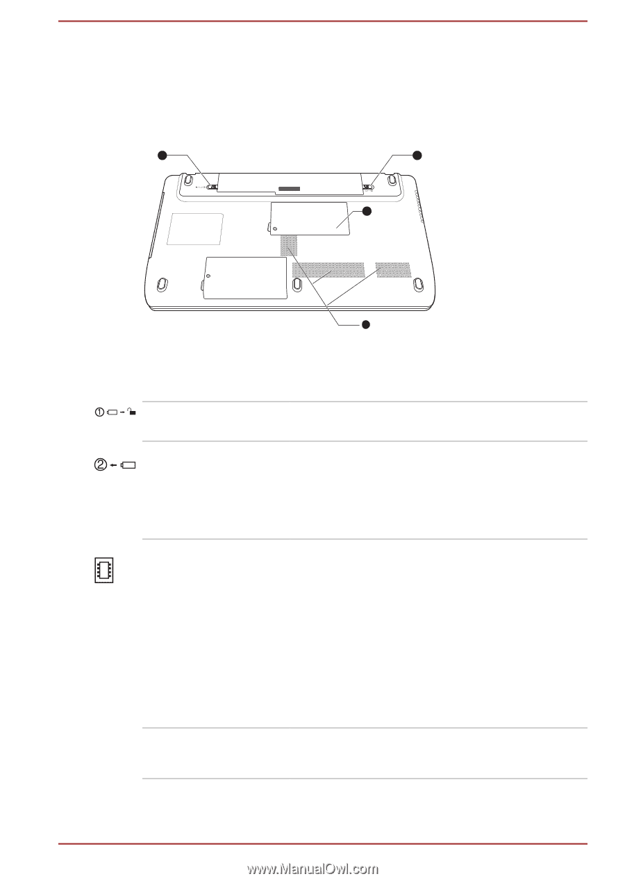
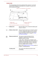
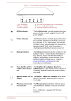
Underside The following figure shows the underside of the computer. You should ensure that the display is closed before the computer is turned over to avoid causing any damage. Figure 2-5 The underside of the computer 1 2 3 1. Battery lock 2. Battery release latch 4 3. Memory module slot 4. Cooling vents Product appearance depends on the model you purchased. Battery lock Slide the battery lock to release the battery pack ready for removal. Battery release latch Slide and hold this latch into its "Unlock" position in order to release the battery pack for removal. For more detailed information on removing the battery pack please refer to Chapter 5, Power and Power-Up Modes. Memory module slot The memory module slot allows for the installation, replacement and removal of additional memory module. 1 GB, 2 GB or 4 GB memory modules can be installed in the computer's two memory slots for a maximum of 8 GB system memory. The actual amount of useable system memory will be less than the installed memory modules. Refer to the Additional memory module section in Chapter 3, Operating Basics. Cooling vents The cooling vents help the processor avoid overheating. User's Manual 2-5
-
 1
1 -
2
-
3
-
4
-
5
-
6
-
7
-
8
-
9
-
10
-
11
-
12
-
13
-
14
-
15
-
16
-
17
-
18
-
19
-
20
-
21
-
22
-
23
-
24
-
25
-
 26
26 -
 27
27 -
 28
28 -
 29
29 -
 30
30 -
 31
31 -
 32
32 -
 33
33 -
 34
34 -
 35
35 -
 36
36 -
37
-
38
-
39
-
40
-
41
-
42
-
43
-
44
-
45
-
46
-
47
-
48
-
49
-
50
-
51
-
52
-
53
-
54
-
55
-
56
-
57
-
58
-
59
-
60
-
61
-
62
-
63
-
64
-
65
-
66
-
67
-
68
-
69
-
70
-
71
-
72
-
73
-
74
-
75
-
76
-
77
-
78
-
79
-
80
-
81
-
82
-
83
-
84
-
85
-
86
-
87
-
88
-
89
-
90
-
91
-
92
-
93
-
94
-
95
-
96
-
97
-
98
-
99
-
100
-
101
-
102
-
103
-
104
-
105
-
106
-
107
-
108
-
109
-
110
-
111
-
112
-
113
-
114
-
115
-
116
-
117
-
118
-
119
-
120
-
121
-
122
-
123
-
124
-
125
-
126
-
127
-
128
-
129
-
130
-
131
-
132
-
133
-
134
-
135
-
136
-
137
-
138
-
139
-
140
-
141
-
142
-
143
-
144
-
145
-
146
-
147
-
148
-
149
-
150
-
151
-
152
-
153
-
154
-
155
-
156
-
157
-
158
-
159
-
160
-
161
-
162
-
163
-
164
-
165
-
166
-
167
-
168
-
169
 |
 |