Toshiba C870 PSC8FC-00800S Users Manual Canada; English - Page 32
Battery lock, Battery release latch, Memory module slot, Cooling vents, Power, and Power-Up Modes
 |
View all Toshiba C870 PSC8FC-00800S manuals
Add to My Manuals
Save this manual to your list of manuals |
Page 32 highlights
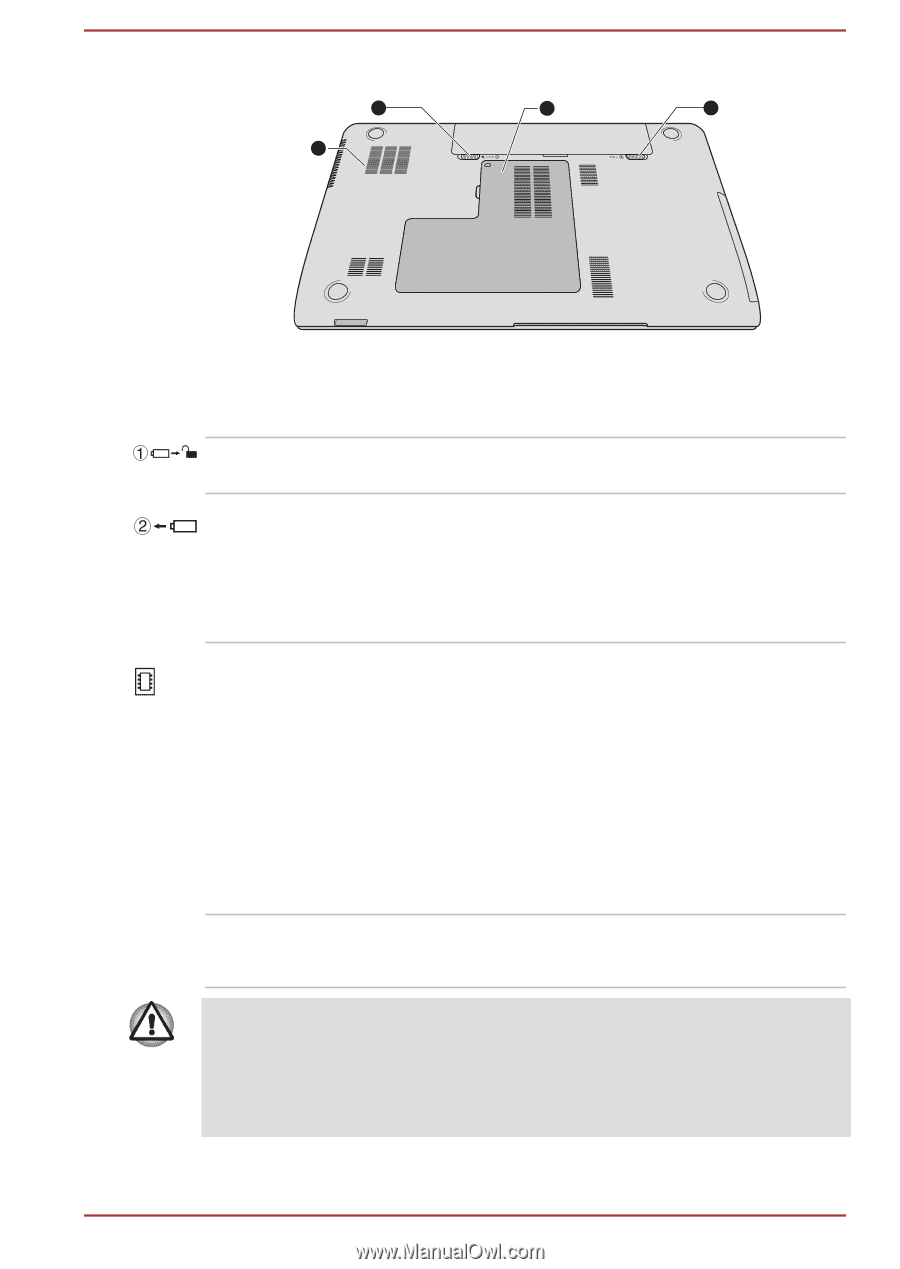
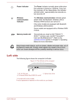
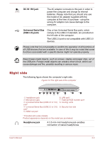
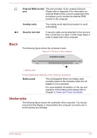
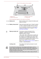
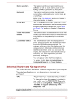
Figure 2-5 The underside of the computer 1 3 2 4 1. Battery lock 2. Battery release latch 3. Memory module slot 4. Cooling vents Product appearance depends on the model you purchased. Battery lock Slide the battery lock to release the battery pack ready for removal. Battery release latch Slide and hold this latch into its "Unlock" position in order to release the battery pack for removal. For more detailed information on removing the battery pack please refer to Chapter 5, Power and Power-Up Modes. Memory module slot The memory module slot allows for the installation, replacement and removal of additional memory module. 1 GB, 2 GB, 4 GB or 8GB memory modules can be installed in the computer's two memory slots for a maximum of 16 GB system memory. The actual amount of useable system memory will be less than the installed memory modules. Refer to the Additional memory module section in Chapter 3, Operating Basics. Cooling vents The cooling vents help the processor to avoid overheating. Do not block the cooling vents. Keep foreign metal objects, such as screws, staples and paper clips, out of the cooling vents. Foreign metal objects can create a short circuit, which can cause damage and fire, possibly resulting in serious injury. Carefully clean the dust on the cooling vents' surface using a soft cloth. User's Manual 2-6
-
 1
1 -
2
-
3
-
4
-
5
-
6
-
7
-
8
-
9
-
10
-
11
-
12
-
13
-
14
-
15
-
16
-
17
-
18
-
19
-
20
-
21
-
22
-
23
-
24
-
25
-
26
-
 27
27 -
 28
28 -
 29
29 -
 30
30 -
 31
31 -
 32
32 -
 33
33 -
 34
34 -
 35
35 -
 36
36 -
 37
37 -
38
-
39
-
40
-
41
-
42
-
43
-
44
-
45
-
46
-
47
-
48
-
49
-
50
-
51
-
52
-
53
-
54
-
55
-
56
-
57
-
58
-
59
-
60
-
61
-
62
-
63
-
64
-
65
-
66
-
67
-
68
-
69
-
70
-
71
-
72
-
73
-
74
-
75
-
76
-
77
-
78
-
79
-
80
-
81
-
82
-
83
-
84
-
85
-
86
-
87
-
88
-
89
-
90
-
91
-
92
-
93
-
94
-
95
-
96
-
97
-
98
-
99
-
100
-
101
-
102
-
103
-
104
-
105
-
106
-
107
-
108
-
109
-
110
-
111
-
112
-
113
-
114
-
115
-
116
-
117
-
118
-
119
-
120
-
121
-
122
-
123
-
124
-
125
-
126
-
127
-
128
-
129
-
130
-
131
-
132
-
133
-
134
-
135
-
136
-
137
-
138
-
139
-
140
-
141
-
142
-
143
-
144
-
145
-
146
-
147
-
148
-
149
-
150
-
151
-
152
-
153
-
154
-
155
-
156
-
157
-
158
-
159
-
160
 |
 |