Toshiba IPS8-1T Hardware Manual - Page 17
Rear Panel Connectors
 |
UPC - 883974230556
View all Toshiba IPS8-1T manuals
Add to My Manuals
Save this manual to your list of manuals |
Page 17 highlights
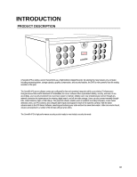
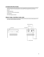
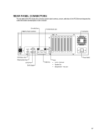
REAR PANEL CONNECTORS The rear panel of the IPS contains the connectors used to attach cameras, sensors, and relays to the IPS. Below are diagrams that outline the location and description of each connector: Fire Wire Port IEEE AC Power Connector RJ-45 Network Jack Cooling Fan PS/2 Mouse Input PS/2 Keyboard Input DVI-D Port SVGA Output USB Ports Audio • Line In - line level • Speaker Out • Microphone In - not used Power Switch 17
-
 1
1 -
2
-
3
-
4
-
5
-
6
-
7
-
8
-
9
-
10
-
11
-
 12
12 -
 13
13 -
 14
14 -
 15
15 -
 16
16 -
 17
17 -
 18
18 -
 19
19 -
 20
20 -
 21
21 -
 22
22 -
23
-
24
-
25
 |
 |

17
REAR PANEL CONNECTORS
The rear panel of the IPS contains the connectors used to attach cameras, sensors, and relays to the IPS. Below are diagrams that
outline the location and description of each connector:
Cooling Fan
Power Switch
IEEE AC Power Connector
PS/2 Mouse Input
PS/2 Keyboard Input
DVI-D Port
SVGA Output
USB Ports
RJ-45 Network Jack
Audio
•
Line In – line level
•
Speaker Out
•
Microphone In – not used
Fire Wire Port