Toshiba MD24F51 User Manual - Page 15
Connecting to optional equipment
 |
View all Toshiba MD24F51 manuals
Add to My Manuals
Save this manual to your list of manuals |
Page 15 highlights
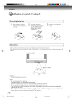
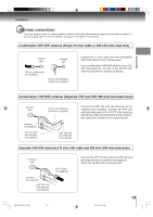
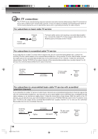
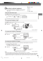
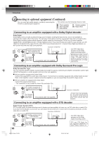
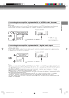
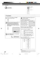
Connecting to optional equipment You can enjoy VCR, camcorder or TV game with connection to external input. To select the external input, press INPUT and select "LINE1" or "LINE2" mode. Using the audio/video inputs Press INPUT repeatedly to select the desired mode. "LINE1", "LINE2" or TV channel will display on the screen for 4 seconds. TV Channel LINE 1 LINE 2 LINE 1 (Back) (Front) INPUT GAME Connections Note: In the DVD mode this key will not operate. To connect the TV/DVD to a VCR Press INPUT to select the desired mode to use the TV as a monitor. Operate your VCR as usual. VCR Rear of TV/DVD : Signal flow VIDEO IN To Audio/Video OUT AUDIO IN (L) AUDIO IN (R) Audio/Video cable (not supplied) Illustration of MD24F51 To connect the TV/DVD to a camcorder To playback from the camcorder, connect the camcorder to the TV/DVD as shown. : Signal flow Camcorder Front of TV/DVD VIDEO IN To Audio/Video OUT Audio/Video cable (not supplied) To connect the TV/DVD to a TV Game AUDIO IN (R) AUDIO IN (L) Illustration of MD24F51 You can enjoy playing a TV game on the screen by adjusting to suitable brightness for your eyes. 1. Connect a TV Game to the TV/DVD. 2. Press GAME. The GAME mode screen appears. • This TV/DVD has the GAME mode function 21 . Front of TV/DVD : Signal flow VIDEO IN To Audio/Video OUT AUDIO IN (R) AUDIO IN (L) Audio/Video cable (not supplied) Notes: Illustration of MD24F51 • You can also change the TV screen to LINE1 or LINE2 by pressing the CH / buttons. • The TV/DVD can also be used as a display device for many video games. However, due to the wide variety of different types of signal generated by these devices and subsequent hook-up variations required, they have not all been included in the suggested connection diagrams. You'll need to consult each component's Owner's Manual for additional information. 15 5S10101A [E] (P13-23) 15 2/5/05, 9:41 AM
-
 1
1 -
2
-
3
-
4
-
5
-
6
-
7
-
8
-
9
-
 10
10 -
 11
11 -
 12
12 -
 13
13 -
 14
14 -
 15
15 -
 16
16 -
 17
17 -
 18
18 -
 19
19 -
 20
20 -
21
-
22
-
23
-
24
-
25
-
26
-
27
-
28
-
29
-
30
-
31
-
32
-
33
-
34
-
35
-
36
-
37
-
38
-
39
-
40
-
41
-
42
-
43
-
44
-
45
-
46
-
47
-
48
-
49
-
50
-
51
-
52
-
53
-
54
-
55
-
56
 |
 |