Toshiba P200 PSPB6C-BW508C Users Manual Canada; English - Page 51
The Grand Tour, Front with the display closed
 |
View all Toshiba P200 PSPB6C-BW508C manuals
Add to My Manuals
Save this manual to your list of manuals |
Page 51 highlights
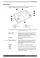
Satellite P200/Satellite Pro P200 Chapter 2 The Grand Tour This chapter identifies the various components of your computer. Become familiar with each component before you operate the computer. Certain types of notebook chassis are designed to accommodate all possible configurations for an entire product series. Your selected model may not have all the features and specifications corresponding to all of the icons or switches shown on the notebook chassis, unless you have selected all those features. Front with the display closed The following figure shows the computer front with its display panel in the closed position. 1 2 345 6 7 8 9 10 11 1. FRONT EDGE LOGO* 2. DC IN LED 3. POWER LED 4. BATTERY LED 5. HARD DISK DRIVE LED 6. MULTIPLE DIGITAL MEDIA CARD SLOT ACCESS LED* 7. WIRELESS COMMUNICATION SWITCH AND LED* 8. MICROPHONE JACK 9. HEADPHONE JACK 10. VOLUME CONTROL 11. MULTIPLE DIGITAL MEDIA CARD SLOT* * The availability of this feature is dependent on the model you purchased. Front of the computer with display closed User's Manual 2-1
-
 1
1 -
2
-
3
-
4
-
5
-
6
-
7
-
8
-
9
-
10
-
11
-
12
-
13
-
14
-
15
-
16
-
17
-
18
-
19
-
20
-
21
-
22
-
23
-
24
-
25
-
26
-
27
-
28
-
29
-
30
-
31
-
32
-
33
-
34
-
35
-
36
-
37
-
38
-
39
-
40
-
41
-
42
-
43
-
44
-
45
-
 46
46 -
 47
47 -
 48
48 -
 49
49 -
 50
50 -
 51
51 -
 52
52 -
 53
53 -
 54
54 -
 55
55 -
 56
56 -
57
-
58
-
59
-
60
-
61
-
62
-
63
-
64
-
65
-
66
-
67
-
68
-
69
-
70
-
71
-
72
-
73
-
74
-
75
-
76
-
77
-
78
-
79
-
80
-
81
-
82
-
83
-
84
-
85
-
86
-
87
-
88
-
89
-
90
-
91
-
92
-
93
-
94
-
95
-
96
-
97
-
98
-
99
-
100
-
101
-
102
-
103
-
104
-
105
-
106
-
107
-
108
-
109
-
110
-
111
-
112
-
113
-
114
-
115
-
116
-
117
-
118
-
119
-
120
-
121
-
122
-
123
-
124
-
125
-
126
-
127
-
128
-
129
-
130
-
131
-
132
-
133
-
134
-
135
-
136
-
137
-
138
-
139
-
140
-
141
-
142
-
143
-
144
-
145
-
146
-
147
-
148
-
149
-
150
-
151
-
152
-
153
-
154
-
155
-
156
-
157
-
158
-
159
-
160
-
161
-
162
-
163
-
164
-
165
-
166
-
167
-
168
-
169
-
170
-
171
-
172
-
173
-
174
-
175
-
176
-
177
-
178
-
179
-
180
-
181
-
182
-
183
-
184
-
185
-
186
-
187
-
188
-
189
-
190
-
191
-
192
-
193
-
194
 |
 |