Toshiba Portege M500 PPM51C-GF501EF Users Manual Canada; English - Page 178
Removing memory module, start, Control Panel, Performance and Maintenance, System, System Properties
 |
View all Toshiba Portege M500 PPM51C-GF501EF manuals
Add to My Manuals
Save this manual to your list of manuals |
Page 178 highlights
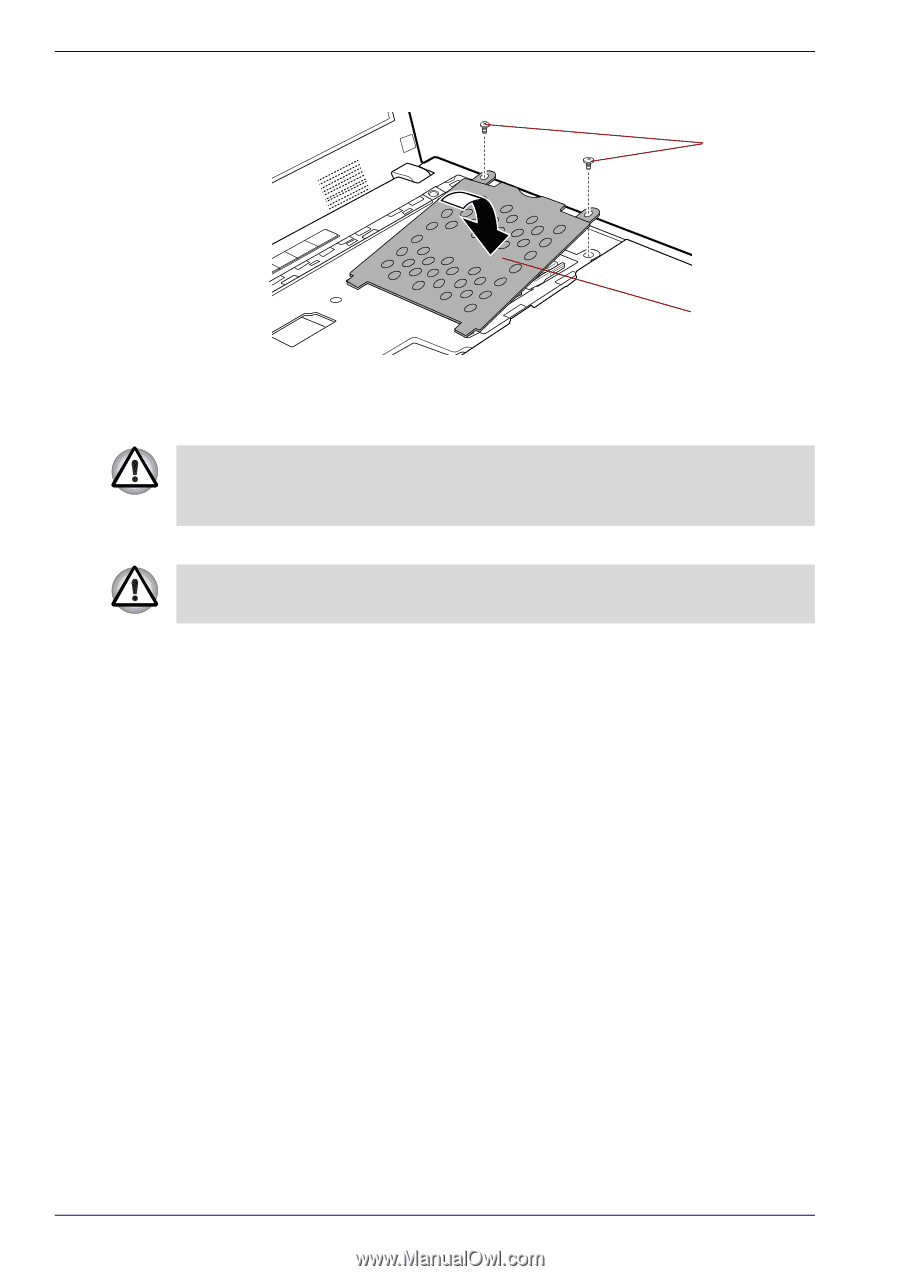
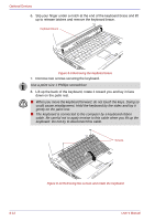
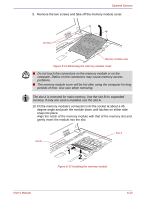
Optional Devices 11. Replace the memory module cover and screw in the two screws. Screws Memory module cover Figure 8-13 Replace the memory module cover 12. Insert the tabs on the front of the keyboard into the corresponding notches on the computer and place the keyboard down. When seating the keyboard, be sure to connect the circuit board if the keyboard ribbon cable was pulled out while you were removing the keyboard. 13. Screw the two screws and secure the keyboard. Be sure to use all two screws removed in step 7. Make sure no screw was dropped into the computer. Make sure no foreign matter can be found. 14. Set the keyboard brace into its groove and press down to secure the latches. 15. Install the battery pack. Refer to Replacing the battery pack section in Chapter 6, Power and Power-Up Modes, for details. 16. Turn your computer over. 17. Turn the power on and make sure the added memory is recognized. Click start, click Control Panel, click Performance and Maintenance and select the System icon. Open System Properties window and click General tab. Removing memory module To remove the memory module, make sure the computer is in boot mode then: 1. Set the computer to boot mode and turn the computer's power off. Make sure the Power indicator is off. 2. Remove AC adaptor and all cables connected to the computer. 3. Turn the computer upside down and remove the battery pack. Refer to Replacing the battery pack section in Chapter 6, Power and Power-Up Modes, for details. 4. Follow steps 4 through 9 in Installing memory module to remove the memory module cover. 5. Push the latches to the outside to release the module. A spring will force one end of the module up. 8-14 User's Manual
-
 1
1 -
2
-
3
-
4
-
5
-
6
-
7
-
8
-
9
-
10
-
11
-
12
-
13
-
14
-
15
-
16
-
17
-
18
-
19
-
20
-
21
-
22
-
23
-
24
-
25
-
26
-
27
-
28
-
29
-
30
-
31
-
32
-
33
-
34
-
35
-
36
-
37
-
38
-
39
-
40
-
41
-
42
-
43
-
44
-
45
-
46
-
47
-
48
-
49
-
50
-
51
-
52
-
53
-
54
-
55
-
56
-
57
-
58
-
59
-
60
-
61
-
62
-
63
-
64
-
65
-
66
-
67
-
68
-
69
-
70
-
71
-
72
-
73
-
74
-
75
-
76
-
77
-
78
-
79
-
80
-
81
-
82
-
83
-
84
-
85
-
86
-
87
-
88
-
89
-
90
-
91
-
92
-
93
-
94
-
95
-
96
-
97
-
98
-
99
-
100
-
101
-
102
-
103
-
104
-
105
-
106
-
107
-
108
-
109
-
110
-
111
-
112
-
113
-
114
-
115
-
116
-
117
-
118
-
119
-
120
-
121
-
122
-
123
-
124
-
125
-
126
-
127
-
128
-
129
-
130
-
131
-
132
-
133
-
134
-
135
-
136
-
137
-
138
-
139
-
140
-
141
-
142
-
143
-
144
-
145
-
146
-
147
-
148
-
149
-
150
-
151
-
152
-
153
-
154
-
155
-
156
-
157
-
158
-
159
-
160
-
161
-
162
-
163
-
164
-
165
-
166
-
167
-
168
-
169
-
170
-
171
-
172
-
 173
173 -
 174
174 -
 175
175 -
 176
176 -
 177
177 -
 178
178 -
 179
179 -
 180
180 -
 181
181 -
 182
182 -
 183
183 -
184
-
185
-
186
-
187
-
188
-
189
-
190
-
191
-
192
-
193
-
194
-
195
-
196
-
197
-
198
-
199
-
200
-
201
-
202
-
203
-
204
-
205
-
206
-
207
-
208
-
209
-
210
-
211
-
212
-
213
-
214
-
215
-
216
-
217
-
218
-
219
-
220
-
221
-
222
-
223
-
224
-
225
-
226
-
227
-
228
-
229
-
230
-
231
-
232
-
233
-
234
-
235
-
236
-
237
-
238
-
239
-
240
-
241
-
242
-
243
-
244
-
245
-
246
-
247
-
248
-
249
-
250
-
251
-
252
-
253
-
254
-
255
-
256
-
257
-
258
-
259
-
260
-
261
-
262
-
263
-
264
-
265
-
266
-
267
-
268
-
269
-
270
-
271
-
272
-
273
-
274
 |
 |