Toshiba SD-R6112 User Manual - Page 13
Drive Connectors -SD-R6012
 |
View all Toshiba SD-R6112 manuals
Add to My Manuals
Save this manual to your list of manuals |
Page 13 highlights
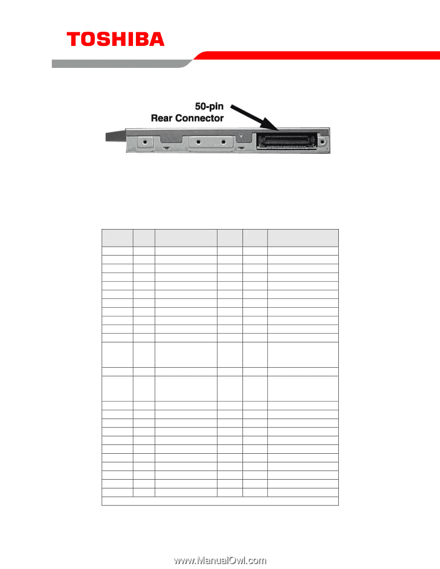
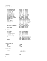
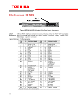
Drive Connectors -SD-R6012 Figure 1.SD-R6012 DVD Writeable Drive Rear Panel - Connector ATAPI A 50-pin ATAPI interface connector is found at the rear of the SD-R6012 DVD rewriteable Connector drive. Connecting cable should use Japan Aviation Electronics Industry Limited KX14- 50Series L or equivalent connector. Table 1.Interface Pin Assignments PIN I/O SIGNAL NAME PIN NO. NO. 1 O Audio L-CH 2 3 Audio Ground 4 5 I /RESET 6 7 I/O DD7 8 9 I/O DD6 10 11 I/O DD5 12 13 I/O DD4 14 15 I/O DD3 16 17 I/O DD2 18 19 I/O DD1 20 21 I/O DD0 22 23 Ground 24 25 I /DIOW:STOP 26 27 O IORDY: / 28 DDMARDY: DSTROBE 29 O INTRQ 30 31 I DA1 32 33 I DA0 34 35 I /CS1FX 36 37 I/O /DASP 38 39 I +5V (Motor) 40 41 I +5V (Logic) 42 43 Ground 44 45 Ground 46 47 I CSEL 48 49 I Vendor Unique* 50 *Vender Unique, don't connect pins I/O SIGNAL NAME O Audio R-CH Digital Ground I/O DD8 I/O DD9 I/O DD10 I/O DD11 I/O DD12 I/O DD13 I/O DD14 I/O DD15 O DMARQ I /DIOR: / HDMARDT: HSTROBE Ground I /DMACK O /IOCS16 I/O /PDIAG I DA2 I /CS3FX I +5V (Motor) I +5V (Motor) I +5V (Logic) Ground Ground Ground I Vendor Unique* 11
-
 1
1 -
2
-
3
-
4
-
5
-
6
-
7
-
 8
8 -
 9
9 -
 10
10 -
 11
11 -
 12
12 -
 13
13
 |
 |