Toshiba Satellite P755 PSAY3C-0CN010 Users Manual Canada; English - Page 43
Battery lock, Battery release latch, Cooling vents, Memory module slot, Power, and Power-Up Modes
 |
View all Toshiba Satellite P755 PSAY3C-0CN010 manuals
Add to My Manuals
Save this manual to your list of manuals |
Page 43 highlights
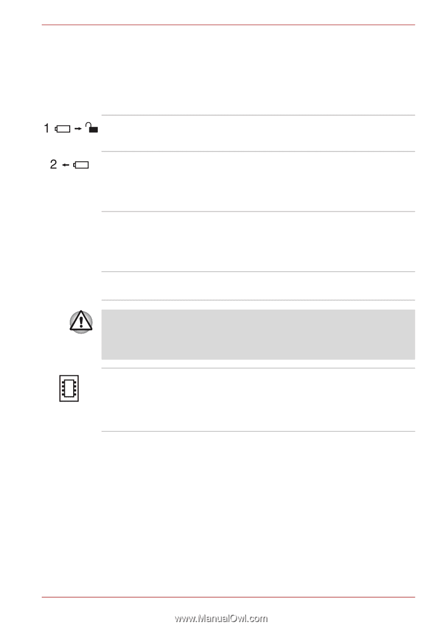
The Grand Tour 1. Battery lock 2. Battery release latch 3. Battery pack 4. Cooling vents 5. Memory module slot Product appearance depends on the model you purchased. Figure 2-5 The underside of the computer Battery lock Slide the battery lock to release the battery pack ready for removal. Battery release latch Slide and hold this latch into its "Unlock" position in order to release the battery pack for removal. For more detailed information on removing the battery pack please refer to Chapter 6, Power and Power-Up Modes. Battery pack The battery pack provides power to the computer when the AC adaptor is not connected. For more detailed information on the use and operation of the battery pack please refer to Chapter 6, Power and Power-Up Modes. Cooling vents The cooling vents help the processor to avoid overheating. Do not block the cooling vents. Keep foreign metal objects, such as screws, staples and paper clips, out of the cooling vents. Foreign metal objects can create a short circuit, which can cause damage and fire, possibly resulting in serious injury Memory module slot The memory module slot allows for the installation, replacement and removal of additional memory module. Refer to the Additional memory module section in Chapter 3, Hardware, Utilities and Options. User's Manual 2-6
-
 1
1 -
2
-
3
-
4
-
5
-
6
-
7
-
8
-
9
-
10
-
11
-
12
-
13
-
14
-
15
-
16
-
17
-
18
-
19
-
20
-
21
-
22
-
23
-
24
-
25
-
26
-
27
-
28
-
29
-
30
-
31
-
32
-
33
-
34
-
35
-
36
-
37
-
 38
38 -
 39
39 -
 40
40 -
 41
41 -
 42
42 -
 43
43 -
 44
44 -
 45
45 -
 46
46 -
 47
47 -
 48
48 -
49
-
50
-
51
-
52
-
53
-
54
-
55
-
56
-
57
-
58
-
59
-
60
-
61
-
62
-
63
-
64
-
65
-
66
-
67
-
68
-
69
-
70
-
71
-
72
-
73
-
74
-
75
-
76
-
77
-
78
-
79
-
80
-
81
-
82
-
83
-
84
-
85
-
86
-
87
-
88
-
89
-
90
-
91
-
92
-
93
-
94
-
95
-
96
-
97
-
98
-
99
-
100
-
101
-
102
-
103
-
104
-
105
-
106
-
107
-
108
-
109
-
110
-
111
-
112
-
113
-
114
-
115
-
116
-
117
-
118
-
119
-
120
-
121
-
122
-
123
-
124
-
125
-
126
-
127
-
128
-
129
-
130
-
131
-
132
-
133
-
134
-
135
-
136
-
137
-
138
-
139
-
140
-
141
-
142
-
143
-
144
-
145
-
146
-
147
-
148
-
149
-
150
-
151
-
152
-
153
-
154
-
155
-
156
-
157
-
158
-
159
-
160
-
161
-
162
-
163
-
164
-
165
-
166
-
167
-
168
-
169
-
170
-
171
-
172
-
173
-
174
-
175
-
176
-
177
-
178
-
179
-
180
-
181
-
182
-
183
-
184
-
185
-
186
-
187
-
188
-
189
-
190
-
191
-
192
-
193
-
194
-
195
-
196
-
197
-
198
-
199
-
200
-
201
-
202
-
203
-
204
-
205
-
206
-
207
-
208
-
209
-
210
-
211
-
212
-
213
-
214
-
215
-
216
-
217
-
218
-
219
-
220
-
221
 |
 |