Toshiba TDP-T98 User Manual - Page 11
Connection, Turning the power on and off - remote
 |
View all Toshiba TDP-T98 manuals
Add to My Manuals
Save this manual to your list of manuals |
Page 11 highlights
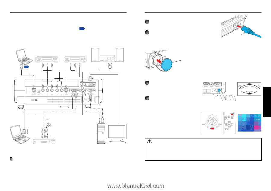
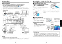
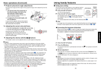
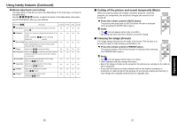
Connection Before connection • Read the owner's manual of the device you are connecting to the projector. • Some types of computer cannot be used or connected to this projector. Check for an RGB output terminal, supported signal p.39 , etc. • Turn off the power of both devices before connecting. • The figure below is a sample connection. This does not mean that all of these devices can or must be connected simultaneously. (Dotted lines mean items can be exchanged.) Computer (for control) VCR Video recorder, DVD player, etc. Audio amplifier, etc. To RS-232C terminal To audio output p.41 White (L)/Red (R) Control cable AV cable (not supplied) To video To audio output output White (L)/Red (R) Video cable (not supplied) S-Video cable (not supplied) To S-Video Audio cable output (not supplied) To audio input White (L)/Red (R) RGB cable (not supplied) Audio cable (not supplied) To RGB output To audio output Monitor cable Mini D-sub 15P-BNC (not supplied) To Y/CB/CR output Green (Y)/Blue (CB)/Red (CR) Conversion adapter BNC-pin (not supplied) Computer DVD video recorder, etc. Audio cable (not supplied) To audio output RGB cable (supplied) To RGB output Computer Notes • COMPUTER terminals 1 and 2 function identically. • The AUDIO IN terminal doubles for devices connected to COMPUTER terminals 1 and 2. 20 Operations Turning the power on and off ■ Connecting the power cord 1 Insert the power cord connector into the AC IN socket of the projector. 2 Insert the power cord plug into a wall or other power outlet. Power cord connector (Supplied) ■ Removing the lens cover Be sure to remove the lens cover when the power is turned on. If it is left on, it could become deformed due to heat. ■ Turning the power on 1 Turn on the main power switch The ON indicator will change to orange, indicating standby mode. 2 Press the ON/STANDBY button. The power turns on, and the following 3 green indicators light: ON, LAMP, and FAN. After a moment, the start-up screen appears. Control panel Remote Control (Orange) Start-up screen CAUTION • Do not look into the lens while the lamp is on. The strong light from the lamp may cause damage to your eyes or sight. • Do not block the air intake or exhaust. Doing so could cause a fire due to internal overheating. • Do not place your hands, face, or other objects near the air exhaust. Doing so could cause burns, deform/break the object. 21 Operations
-
 1
1 -
2
-
3
-
4
-
5
-
 6
6 -
 7
7 -
 8
8 -
 9
9 -
 10
10 -
 11
11 -
 12
12 -
 13
13 -
 14
14 -
 15
15 -
 16
16 -
17
-
18
-
19
-
20
-
21
-
22
 |
 |