Toshiba Tecra 9000 Replacement Instructions - Page 8
Cooling Module Removal, Cpu Removal, Microphone Removal, Sd/sound Board Removal - no sound
 |
View all Toshiba Tecra 9000 manuals
Add to My Manuals
Save this manual to your list of manuals |
Page 8 highlights
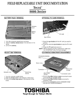
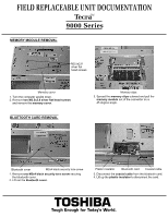
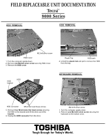
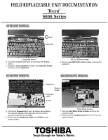
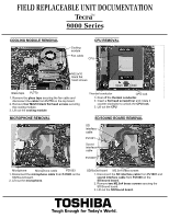
FIELD REPLACEABLE UNIT DOCUMENTATION TecraTM 9000 Series COOLING MODULE REMOVAL CPU REMOVAL Cooling module Fan cable CPU M2.5x10 black flat head screws Open Close Glass tape PJ770 1. Remove the glass tape securing the fan cable and disconnect the cable from PJ770 on the top board. 2. Remove four M2x10 black flat head screws securing the cooling module. 3. Lift out the cooling module. Thermal conductor CPU lock 1. Peel off the thermal conductor. 2. Insert a flat head screwdriver and rotate it counter-clockwise to unlock the CPU lock. 3. Lift out the CPU. MICROPHONE REMOVAL SD/SOUND BOARD REMOVAL SD interface cable PJ1001 Sound interface cable PJ1000 Microphone Microphone cable PJ1003 1. Disconnect the microphone cable from PJ1003 on the SD/Sound board. 2. Lift out the microphone. SD/Sound board M2.5x4 brass screws 1. Disconnect the SD interface cable from PJ1001 and sound interface cable from PJ1000 on the SD/sound board. 2. Remove two M2.5x4 brass screws securing the SD/Sound board. 3. Lift out the SD/Sound board. TOSHIBA Tough Enough for Today's World.
-
 1
1 -
2
-
 3
3 -
 4
4 -
 5
5 -
 6
6 -
 7
7 -
 8
8 -
 9
9 -
 10
10 -
 11
11
 |
 |
