Toshiba Tecra A50-C PS569C-02U006 Users Manual Canada; English - Page 39
Battery lock, Battery release latch, Cooling vents, screws, staples, and paper clips
 |
View all Toshiba Tecra A50-C PS569C-02U006 manuals
Add to My Manuals
Save this manual to your list of manuals |
Page 39 highlights
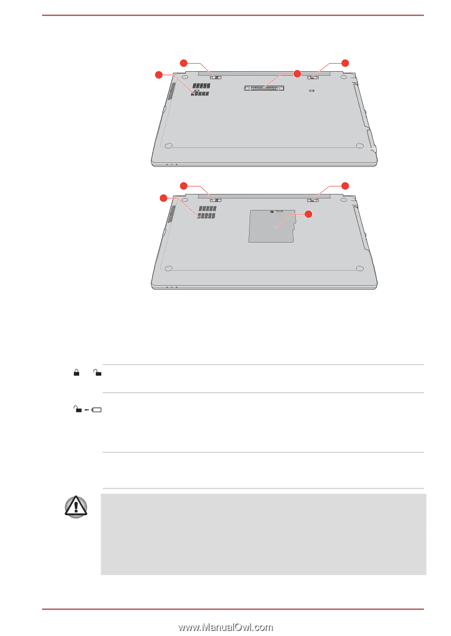
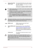
Figure 3-5 The underside of the computer 1 3 2 4 1 3 2 5 1. Battery lock 2. Battery release latch 3. Cooling vents 4. Docking port* 5. Memory module cover* * Provided with some models. Product appearance depends on the model you purchased. 1 Battery lock Slide the battery lock to release the battery pack ready for removal. 2 Battery release latch Slide and hold this latch into its "Unlock" position in order to release the battery pack for removal. For more detailed information on removing the battery pack, refer to the Battery section. Cooling vents The cooling vents help the processor to avoid overheating. Do not block the cooling vents. Keep foreign metal objects, such as screws, staples, and paper clips, out of the cooling vents. Foreign metal objects can create a short circuit, which can cause damage and fire, possibly resulting in serious injury. Carefully clean the dust on the surface of the cooling vents using a soft cloth. User's Manual 3-7
-
 1
1 -
2
-
3
-
4
-
5
-
6
-
7
-
8
-
9
-
10
-
11
-
12
-
13
-
14
-
15
-
16
-
17
-
18
-
19
-
20
-
21
-
22
-
23
-
24
-
25
-
26
-
27
-
28
-
29
-
30
-
31
-
32
-
33
-
 34
34 -
 35
35 -
 36
36 -
 37
37 -
 38
38 -
 39
39 -
 40
40 -
 41
41 -
 42
42 -
 43
43 -
 44
44 -
45
-
46
-
47
-
48
-
49
-
50
-
51
-
52
-
53
-
54
-
55
-
56
-
57
-
58
-
59
-
60
-
61
-
62
-
63
-
64
-
65
-
66
-
67
-
68
-
69
-
70
-
71
-
72
-
73
-
74
-
75
-
76
-
77
-
78
-
79
-
80
-
81
-
82
-
83
-
84
-
85
-
86
-
87
-
88
-
89
-
90
-
91
-
92
-
93
-
94
-
95
-
96
-
97
-
98
-
99
-
100
-
101
-
102
-
103
-
104
-
105
-
106
-
107
-
108
-
109
-
110
-
111
-
112
-
113
-
114
-
115
-
116
-
117
-
118
-
119
-
120
-
121
-
122
-
123
-
124
-
125
-
126
-
127
-
128
-
129
-
130
-
131
-
132
-
133
-
134
-
135
-
136
-
137
-
138
-
139
-
140
-
141
-
142
-
143
-
144
-
145
-
146
-
147
 |
 |