Toshiba Tecra R850 User Manual - Page 36
Front with the display open (R850), Battery lock, Battery release latch, Docking port - port replicator
 |
View all Toshiba Tecra R850 manuals
Add to My Manuals
Save this manual to your list of manuals |
Page 36 highlights
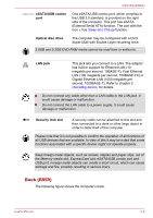
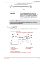
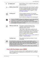
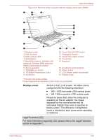
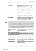
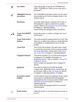
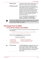
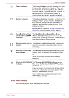
R850/R840/R830 Battery lock Slide the battery lock to release the battery pack ready for removal. Battery release latch Slide and hold this latch into its "Unlock" position in order to release the battery pack for removal. For more detailed information on removing the battery pack please refer to Chapter 5, Power and Power-Up Modes. Docking port This port enables connection of an optional TOSHIBA Hi-Speed Port Replicator II described in chapter 3, Operating Basics. Some models are equipped with a Docking port. Only the TOSHIBA Hi-Speed Port Replicator II can be used with this computer. Do not attempt to use any other Port Replicator. Keep foreign objects out of the docking port. A pin or similar object can damage the computer's circuitry. Memory module slot The memory module slot allows for the installation, replacement and removal of additional memory module. 1 GB, 2 GB or 4 GB memory modules can be installed in the computer's two memory slots for a maximum of 8 GB system memory. The actual amount of useable system memory will be less than the installed memory modules. Refer to the Additional memory module section in Chapter 3, Operating Basics. Cooling vents The cooling vents help the processor to avoid overheating. Do not block the cooling vents. Keep foreign metal objects, such as screws, staples and paper clips, out of the cooling vents. Foreign metal objects can create a short circuit, which can cause damage and fire, possibly resulting in serious injury. Carefully clean the dust on the cooling vents' surface using a soft cloth. Front with the display open (R850) This section shows the computer with the display panel open. In order to open the display, lift the display panel up and position it at a comfortable viewing angle for you. User's Manual 2-8
-
 1
1 -
2
-
3
-
4
-
5
-
6
-
7
-
8
-
9
-
10
-
11
-
12
-
13
-
14
-
15
-
16
-
17
-
18
-
19
-
20
-
21
-
22
-
23
-
24
-
25
-
26
-
27
-
28
-
29
-
30
-
 31
31 -
 32
32 -
 33
33 -
 34
34 -
 35
35 -
 36
36 -
 37
37 -
 38
38 -
 39
39 -
 40
40 -
 41
41 -
42
-
43
-
44
-
45
-
46
-
47
-
48
-
49
-
50
-
51
-
52
-
53
-
54
-
55
-
56
-
57
-
58
-
59
-
60
-
61
-
62
-
63
-
64
-
65
-
66
-
67
-
68
-
69
-
70
-
71
-
72
-
73
-
74
-
75
-
76
-
77
-
78
-
79
-
80
-
81
-
82
-
83
-
84
-
85
-
86
-
87
-
88
-
89
-
90
-
91
-
92
-
93
-
94
-
95
-
96
-
97
-
98
-
99
-
100
-
101
-
102
-
103
-
104
-
105
-
106
-
107
-
108
-
109
-
110
-
111
-
112
-
113
-
114
-
115
-
116
-
117
-
118
-
119
-
120
-
121
-
122
-
123
-
124
-
125
-
126
-
127
-
128
-
129
-
130
-
131
-
132
-
133
-
134
-
135
-
136
-
137
-
138
-
139
-
140
-
141
-
142
-
143
-
144
-
145
-
146
-
147
-
148
-
149
-
150
-
151
-
152
-
153
-
154
-
155
-
156
-
157
-
158
-
159
-
160
-
161
-
162
-
163
-
164
-
165
-
166
-
167
-
168
-
169
-
170
-
171
-
172
-
173
-
174
-
175
-
176
-
177
-
178
-
179
-
180
-
181
-
182
-
183
-
184
-
185
-
186
-
187
-
188
-
189
-
190
-
191
-
192
-
193
-
194
-
195
-
196
-
197
-
198
-
199
-
200
-
201
-
202
-
203
-
204
-
205
-
206
-
207
-
208
 |
 |