Tripp Lite 0SU22081 Owner's Manual for Minicom Cat5 KVM Switches 933193 - Page 12
Avoiding general rack mounting problems, 6.2 Rack mounting the Smart CAT5
 |
View all Tripp Lite 0SU22081 manuals
Add to My Manuals
Save this manual to your list of manuals |
Page 12 highlights
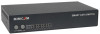
SMART CAT5 SWITCH - 108/116 3.6.1 Avoiding general rack mounting problems Elevated operating ambient temperature The operating ambient temperature of the rack environment may be greater than the room ambient when installing into a closed or multi-unit rack assembly. So install the equipment in an environment compatible with the maximum rated ambient temperature. Reduced airflow Install the equipment in a rack in such a way that the amount of airflow required for safe operation is not compromised. Mechanical loading Mount the equipment in the rack in such a way that a hazardous condition is not achieved due to uneven mechanical loading. Circuit overloading When connecting the equipment to the supply circuit, consider the effect that overloading of circuits might have on over-current protection and supply wiring. Reliable earthing of rack-mounted equipment should be maintained. Give attention to supply connections other than direct connections to the branch circuit (e.g. use of power strips). 3.6.2 Rack mounting the Smart CAT5 The Smart CAT5 comes with screw holes on the side for easy rack mounting, see figure below. Screw holes for bracket Figure 9 Screw holes for rack mounting Use the L-shaped brackets and screws provided to mount the Smart CAT5 on a server rack as illustrated below. The length of the screws used for connecting the brackets to the Smart CAT5 unit must not exceed 5 mm. 11
-
 1
1 -
2
-
3
-
4
-
5
-
6
-
 7
7 -
 8
8 -
 9
9 -
 10
10 -
 11
11 -
 12
12 -
 13
13 -
 14
14 -
 15
15 -
 16
16 -
 17
17 -
18
-
19
-
20
-
21
-
22
-
23
-
24
-
25
-
26
-
27
-
28
-
29
-
30
-
31
-
32
-
33
-
34
-
35
-
36
-
37
-
38
-
39
-
40
-
41
-
42
-
43
-
44
-
45
 |
 |
