Tripp Lite 0SU22082 Quick Start Guide for Minicom Cat5 KVM Switches 933194 - Page 2
The Smart CAT5 system configuration, The Smart CAT5 models, Pre-installation guidelines
 |
View all Tripp Lite 0SU22082 manuals
Add to My Manuals
Save this manual to your list of manuals |
Page 2 highlights
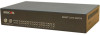
SMART CAT5 SWITCH - 108/116 3. The Smart CAT5 system configuration Figure 1 illustrates the basic configuration of the Smart CAT5 system. SMART CAT5 SWITCH 116 www.minicom.com COMPUTER 9 10 11 12 13 14 15 16 POWER 100-240 VAC 50/60 Hz 1 2 3 4 5 6 7 8 Workstation MIN ICOM To servers RoC/RICCs to servers Figure 1 Smart CAT5 system configuration 4. The Smart CAT5 models The figure below illustrates the rear panel of the Smart CAT5 116. The 108 model is the same but with only 8 Computer ports. www.minicom.com COMPUTER 9 10 11 12 13 14 15 16 POWER 100-240 VAC 50/60 Hz 1 2 3 4 5 6 7 8 Figure 2 Smart CAT5 116 rear panel 5. Pre-installation guidelines Switch off all computers Place cables away from fluorescent lights, air conditioners, and machines that are likely to generate electrical noise Ensure that the maximum distance between each computer and the Smart CAT5, does not exceed 10m/33ft 1
-
 1
1 -
 2
2 -
 3
3 -
 4
4
 |
 |
